Your ESP8266 Needs More Memory

We just got through reviewing MicroPython on the ESP8266, and one of the main takehomes is that our ESP modules need more flash memory. You may be in the same boat — the earliest (and cheapest) modules on the market only had 512 kB of flash. For over-the-air programming, or to give you some more space for fancier programs, you’re going to want 1 MB or even 4 MB.

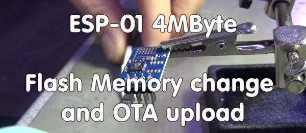
The solution? Just buy a new flash chip and solder it on. This is especially easy if you’ve got an ESP-01, ESP-03, or ESP-11 modules where the flash chip is exposed. Desolder, resolder, done. It can be a little trickier for those modules with a tin can around chips, but that’s nothing that a little hot air can’t fix. See the video embedded below for a good walk-through.

Continue reading “Your ESP8266 Needs More Memory”

A Better Way To Plug A CPLD Into A Breadboard

If you read my first post about a simple CPLD do-it-yourself project you may remember that I seriously wiffed when I made the footprint 1” wide, which was a bit too wide for common solderless breadboards. Since then I started over, having fixed the width problem, and ended up with a module that looks decidedly… cuter.

To back up a little bit, a Complex Programmable Logic Device (CPLD) is a cool piece of hardware to have in your repertoire and it can be used to learn logic or a high level design language or replace obsolete functions or chips. But a CPLD needs a little bit of support infrastructure to become usable, and that’s what I’ll be walking you through here. So if you’re interested in learning CPLDs, or just designing boards for them, read on!

Continue reading “A Better Way To Plug A CPLD Into A Breadboard”

Programmable Logic: Build Yourself A CPLD Module

A Complex Programmable Logic Device (CPLD) is a great piece of hardware to have in your repertoire. As its name implies, you can program these chips to serve the logic functions you need. This might be replacing an obsolete chip, or maybe just a way to learn and try different techniques. What better way to learn than to get your hands on a CPLD and give it a try?

I created a CPLD module with the intent of being able to plug it into lots of things including solderless breadboards, but I screwed up. It seems that the plugin space available on a solderless breadboard is 1.1”, I had made the footprint 1” wide leaving no room for a row of wires on both sides. Duh.

But let me back up and show more about what I’m doing , I wanted to make a programmable piece of logic that could be built as a kit one could easily solder at home, could be programmed in-circuit, and could work at 3.3 or 5 volts.

Image5bTo implement an easily solderable kit I went with an older CPLD part that also has 3.3v and 5v versions that will maintain its programming regardless of power. The logic itself is a CPLD IC from the Altera Max family with two versions that fit the board with either 32 or 64 macrocells. A macrocell is the basic logic building block and it is programmed with logic “terms” and then interconnected to other macrocells through a programmable interconnect.

Continue reading “Programmable Logic: Build Yourself A CPLD Module”

Wireless Water Level Sensor From PVC Pipe

[Bob] was having trouble keeping up with his water troughs. He had to constantly check them to make sure they weren’t empty, and he always found that the water level was lower than he thought. He decided it was time to build his own solution to this problem. What he ended up with was a water level sensor made from PVC pipe and a few other components.

The physical assembly is pretty simple. The whole structure is made from 1/2″ PVC pipe and fittings and is broken into four nearly identical sensor modules. The sensors have an electrode on either side. The electrodes are made from PVC end caps, sanded down flat at the tip. A hole is then drilled through the cap to accommodate a small machine screw. The screw threads are coated in joint compound before the screw is driven into the hole, creating its own threads. These caps are placed onto small sections of PVC pipe, which in turn connect to a four-way PVC cross connector. 

On the inside of the electrode cap, two washers are placed onto the screw. A stranded wire is placed between the washers and then clamped in place with a nut. All of the modules are connected together with a few inches of pipe. [Bob] measured this out so it would fit appropriately into his trough, but the measurements can easily be altered to fit just about any size container. The wires all route up through the pipe. The PVC pipe is cemented together to keep the water out. The joint compound prevents any leaks at the electrodes.

A piece of CAT 5 cable connects the electrodes to the electronics inside of the waterproof controller box. The electronics are simple. It’s just a simple piece of perfboard with an XBee and a few transistors. The XBee can detect the water level by testing for a closed circuit between the two electrodes of any sensor module. The water acts as a sort of switch that closes the circuit. When the water gets too low, the circuit opens and [Bob] knows that the water level has lowered. The XBee is connected to a directional 2.4GHz antenna to ensure the signal reaches the laptop several acres away. Continue reading “Wireless Water Level Sensor From PVC Pipe”

RasPi Power Controller

WiFi Controlled Power Outlets With Raspberry Pi

[Tim] was looking for a way to control his power outlets using WiFi. He looked into purchasing a WeMo but he realized that he could build something even better with more bang for his buck. He started out by purchasing a five pack of Etekcity wireless remote control outlet switches. These are kind of like the WeMo, only they aren’t controlled via WiFi. Instead, they come with an RF controller. [Tim] just needed to find a way to bridge the gap between the RF remote and WiFi.

[Tim] decided to use a Raspberry Pi as the brains of the controller. He also purchased a SMAKN 433MHz RF receiver and transmitter for communicating with the wireless outlet switches. The wiring for the modules is pretty simple. There are only four wires. There are power and ground wires for each module. Then the transmitter needs two GPIO pins while the receiver only needs one.

[Tim] began with a fresh installation of Raspbian. He then installed Wiring Pi, which gives you the ability to interface with the GPIO pins in a way that is similar to Arduino. He also installed Apache and PHP to create a web interface for switching the outlets. The last step was to write some custom software. The software included a script that allowed [Tim] to sniff out the controls of his RF remote. The correct codes are entered into the “toggle.php” file, and everything is set. All [Tim] has to do now is browse to his Pi’s web server and click a button. All of the custom code is available via git.

ESP Gets FCC And CE

The ESP8266 Internet of Things module is the latest and greatest thing to come out of China. It’s ideal for turning plastic Minecraft blocks into Minecraft servers, making your toilet tweet, or for some bizarre home automation scheme. This WiFi module is not, however, certified by the FCC. The chipset, on the other hand, is.

Having a single module that’s able to run code, act as a UART to WiFi transceiver, peek and poke a few GPIOs, all priced at about $4 is a game changer, and all your favorite silicon companies are freaking out wondering how they’re going to beat the ESP8266. Now the chipset is FCC certified, the first step to turning these modules into products.

This announcement does come with a few caveats: the chipset is certified, not the module. Each version of the module must be certified by itself, and there are versions that will never be certified by the FCC. Right now, we’re looking at the ESP8266-06, -07, -08, and -12 modules – the ones with a metal shield – as being the only ones that could potentially pass an FCC cert. Yes, those modules already have an FCC logo on them, but you’re looking at something sold for under $5 in China, here.

Anyone wanting to build a product with the ESP will, of course, also need to certify it with the FCC. This announcement hasn’t broken down any walls, but it has cracked a window.

RasPiCommPlus, An Expansion Board For Expansion Boards

The easiest way to connect a GSM module to a Raspberry Pi would be to buy a breakout module, install some software, and connect to a mobile network with a Pi. Need GPS, too? That’s a whole other module, with different software. The guys behind RasPiCommPlus are working on a better solution – a breakout board for breakout boards that takes care of plugging a ton of modules into a Pi and sorts out the kernel drivers to make interfacing with these modules easy.

Right now, the team has a GPS and GSM module, digital in and out modules, an analog input module, and RS-232 and -485 modules. They’re working on some cool additions to the lineup, including a breakout for Sharp memory displays, a 9-axis IMU, a stepper motor driver, and a 1-wire breakout module.

Some of the RasPiCommPlus team showed up to the Hackaday Munich party and were kind enough to sit down for a demo video. You can check that out below.

Continue reading “RasPiCommPlus, An Expansion Board For Expansion Boards”