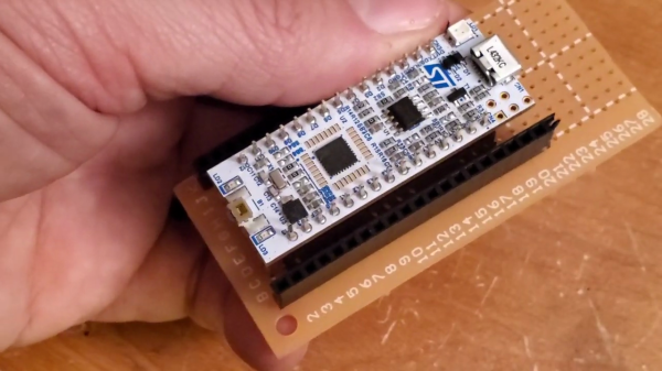
Snoopy Come Home: The Search For Apollo 10

When it comes to the quest for artifacts from the Space Race of the 1960s, few items are more sought after than flown hardware. Oh sure, there have been stories of small samples of the 382 kg of moon rocks and dust that were returned at the cost of something like $25 billion making it into the hands of private collectors, and chunks of the moon may be the ultimate collector’s item, but really, at the end of the day it’s just rock and dust. The serious space junkie wants hardware – the actual pieces of human engineering that helped bring an epic adventure to fruition, and the closer to the moon the artifact got, the more desirable it is.

Sadly, of the 3,000,000 kg launch weight of a Saturn V rocket, only the 5,600 kg command module ever returned to Earth intact. The rest was left along the way, mostly either burned up in the atmosphere or left on the surface of the Moon. While some of these artifacts are recoverable – Jeff Bezos himself devoted a portion of his sizable fortune to salvage one of the 65 F1 engines that were deposited into the Atlantic ocean – those left on the Moon are, for now, unrecoverable, and in most cases they are twisted heaps of wreckage that was intentionally crashed into the lunar surface.

But at least one artifact escaped this ignominious fate, silently orbiting the sun for the last 50 years. This lonely outpost of the space program, the ascent stage from the Apollo 10 Lunar Module, appears to have been located by a team of amateur astronomers, and if indeed the spacecraft, dubbed “Snoopy” by its crew, is still out there, it raises the intriguing possibility of scoring the ultimate Apollo artifact by recovering it and bringing it back home.

Continue reading “Snoopy Come Home: The Search For Apollo 10”

Raspberry Pi Zero Stepper Driver, First Of Many Modules

The Raspberry Pi in general (and the Zero W model in particular) are wonderful pieces of hardware, but they’re not entirely plug-and-play when it comes to embedded applications. The user is on the hook for things like providing a regulated power source, an OS, and being mindful of proper shutdown and ESD precautions. Still, the capabilities make it worth considering and [Alpha le ciel] has a project to make implementation easier with the Raspberry Pi Zero W Stepper Motor Module, which is itself part of a larger project plan to make the Pi Zero W into a robust building block for robotic and CNC applications.

[Alpha le ciel] is building this stepper motor module as the first of many Raspberry Pi hats meant to provide the Raspi with the hardware for robotics applications. This module, in particular, features two A4988 stepper motor drivers, a connector for a power supply or battery providing 7-20V, and a buck converter to bring that power down to the 5V needed by the Pi itself. All the relevant pins are broken out onto the Pi’s GPIO header, making this module the simplest way possible to add a pair of motors to a Pi. What does that mean? Printers or self-balancing robots, really whatever you want.

A stepper driver that conforms to the footprint of the Pi Zero is a good start, and the larger concept of creating additional modules is a worthy entry to the Hackaday Prize.

Debouncing The Old-Fashioned Way

If you were given the task of designing a computer at a time when computers weren’t really even a thing, how would you start? How would you take a collection of vacuum tubes, passive components, and a precious few germanium diodes and engineer something to sell to customers looking for an “electronic brain”?

Where there’s a paycheck, there’s a way, and computer archeologist [Ken Shirriff] laid his hands on some old IBM hardware that tells us a lot about how engineers thought in the earliest days of the computer industry. The gear is a pluggable module from IBM, one of hundreds that once went into their Model 705 computer from the mid-1950s. The particular module [Ken] has is a 5-channel contact debouncer, or in Big Blue’s mid-century parlance, a “Contact-Operated Trigger.” It was used to debounce five of the many, many mechanical contacts in the machine, both buttons and relays, and used eight dual triode tubes to do it. Other modules with the exact same footprint formed the flip-flops, inverters, buffers and clocks needed to build a computer.

[Ken]’s analysis of the debouncer is a fascinating look at what was possible with the technology of the day, and the fact that it led to a standardized framework for generic modules that were actually hot-swappable with what essentially was a zero insertion force plug was quite a feat of engineering. And as a bonus, [Ken] and friends actually got the module up in running in the video after the break.

Jonesing for more retro-computer pluggable goodness? Check out this reproduction IBM flip-flop module from the 1940s.

Continue reading “Debouncing The Old-Fashioned Way”

Sneak Thieves Beware: A Pi Watcheth

Ever have that strange feeling that somebody is breaking into your workshop? Well, Hackaday.io user [Kenny] has whipped up a tutorial on how to scratch that itch by turning a spare Raspberry Pi you may have kicking around into a security camera system that notifies you at a moment’s notice.

The system works like this: a Raspberry Pi 3 and connected camera module remain vigilant, constantly scanning for motion and recording video. If motion is detected, it immediately snaps and sends a picture to the user’s mobile via PushBullet, then begins recording video. If there is still movement after a few seconds, the process repeats until the area is once again devoid of motion. This also permits a two-way communication with your Pi security system, so you can check in on the live feed whenever you feel the urge.

To get this working for you — assuming that your Pi has been recently updated — setup requires setting up a PushBullet account as well as installing it on your mobile and  linking it with an API. For your Pi, you can go ahead with setting up some Python PushBullet libraries, installing FFmpeg, Pi Camera Notifier, and others. Or, install the ready-to-go image [Kenny] has prepared. He gets into the nitty-gritty of the code in his guide, so check that out or watch the tutorial video after the break.

Continue reading “Sneak Thieves Beware: A Pi Watcheth”

Reprogramming Bluetooth Headphones For Great Justice

Like a lot of mass-produced consumer goods, it turns out that the internal workings of Bluetooth headphones are the same across a lot of different brands. One common Bluetooth module is the CSR8645, which [lorf] realized was fairly common and (more importantly) fairly easy to modify. [lorf] was able to put together a toolkit to reprogram this Bluetooth module in almost all of these headphones.

This tip comes to us from [Tigox] who has already made good use of [lorf]’s software. Using the toolkit, he was able to reprogram his own Bluetooth headphones over a USB link to his computer. After downloading and running [lorf]’s program, he was able to modify the name of the device and, more importantly, was able to adjust the behavior of the microphone’s gain which allowed him to have a much more pleasant user experience.

Additionally, the new toolkit makes it possible to flash custom ROMs to CSR Bluetooth modules. This opens up all kinds of possibilities, including the potential to use a set of inexpensive headphones for purposes other than listening to music. The button presses and microphones can be re-purposed for virtually any task imaginable. Of course, you may be able to find cheaper Bluetooth devices to repurpose, but if you just need to adjust your headphones’ settings then this hack will be more useful.

[Featured and Thumbnail Image Source by JLab Audio LLC – jlabaudio.com, CC BY-SA 4.0]

Characterizing A Cheap 500MHz Counter Module

An exciting development over the last few years has been the arrival of extremely cheap instrumentation modules easily bought online and usually shipped from China. Some of them have extremely impressive paper specifications for their price, and it was one of these that caught the eye of [Carol Milazzo, KP4MD]. A frequency counter for under $14 on your favourite online retailer, and with a claimed range of 500 MHz. That could be a useful instrument in its own right, and with a range that significantly exceeds the capabilities of much more expensive bench test equipment from not so long ago.

Just how good is it though, does it live up to the promise? [Carol] presents the measurements she took from the device, so you can see for yourselves. She took look at sensitivity, VSWR, and input impedance over a wide range, after first checking its calibration against a GPS-disciplined standard and making a fine adjustment with its on-board trimmer.

In sensitivity terms it’s a bit deaf, requiring 0.11 Vrms for a lock at 10 MHz. Meanwhile its input impedance decreases from 600 ohms at the bottom of its range to 80 ohms at 200 MHz, with a corresponding shift in VSWR. So it’s never going to match a high-end bench instrument from which you’d expect much more sensitivity and a more stable impedance, but for the price we’re sure that’s something you can all work around. Meanwhile it’s worth noting from the pictures she’s posted that the board has unpopulated space for an SPI interface header, which leaves the potential for it to be used as a logging instrument.

We think it’s worth having as much information as possible about components like this one, both in terms of knowing about new entrants to the market and in knowing their true performance. So if you were curious about those cheap frequency counter modules, now thanks to [Carol] you have some idea of what they can do.

While it’s convenient to buy a counter module like this one, of course there is nothing to stop you building your own. We’ve featured many over the years, this 100MHz one using a 74-series prescaler or this ATtiny offering for example, or how about this very accomplished one with an Android UI?

Apollo: The Alignment Optical Telescope

The Apollo program is a constant reminder that we just don’t need so much to get the job done. Sure it’s easier with today’s tools, but hard work can do it too. [Bill Hammack] elaborates on one such piece of engineering: The Alignment Optical Telescope.

The telescope was used to find the position of the Lunar Module in space so that its guidance computer could do the calculations needed to bring the module home. It does this using techniques that we’ve been using for centuries on land and still use today in space; although now it’s done with computer vision. It was used to align the craft to the stars. NASA used stars as the fixed reference points for the coordinate system used to locate objects in space. But how was this accomplished with great precision?

The alignment optical telescope did this by measuring two unknowns needed by the guidance computer. The astronaut would find the first value by pointing the telescope in the general area necessary to establish a reading, then rotate the first reticle (a horizontal line) on the telescope until it touched the correct star. A ring assembly was then adjusted, moving an Archimedes spiral etched onto the viewfinder. When the spiral touches the star you can read the second value, established by how far the ring has been rotated.

If you’ve ever seen the Lunar Module in person, your first impression might be to giggle a bit at how crude it is. The truth is that much of that crudeness was hard fought to achieve. They needed the simplest, lightest, and most reliable assembly the world had ever constructed. As [Bill Hammack] states at the end of the video, breaking the complicated tool usually used into two simple dials is an amazing engineering achievement.

Continue reading “Apollo: The Alignment Optical Telescope”