Just How Dodgy Are Cheap USB Chargers Anyway?

Aside from apparently having both the ability to reproduce on their own and simultaneously never being around when you need one, USB chargers seem innocuous enough. The specs are simple: convert mains voltage to 5 volts, and don’t kill anyone while doing it. Both specs are typically met by most designs, but judging by [DiodeGoneWild]’s latest USB charger teardown, the latter only just barely, and with a whole lot of luck.

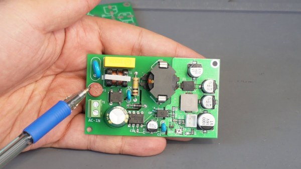
The sad state of plug-in USB power supplies is one of [DiodeGoneWild]’s pet gripes, and deservedly so. Most USB chargers cram a lot of electronics into a mighty small volume, and are built to a price point, meaning that something has to give in the design. In the case of the two units he tears apart in the video below, it’s pretty clear where the compromises are. Neither unit met the specs on the label in terms of current supplied and voltage regulation, even the apparently more capable quick charger, which is the first to go under the knife. The PCB within holds some alarming surprises, like the minimal physical isolation between the mains part of the circuit and the low-voltage section, but the real treat is the Schottky diode that gets up to 170°C under full load. Safety tip: when you smell plastic burning, throw the thing out.

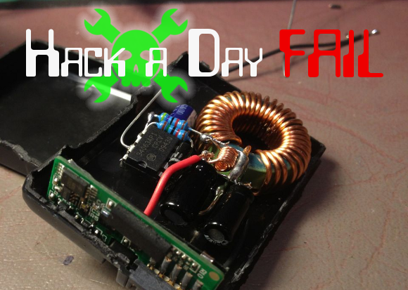
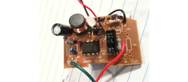
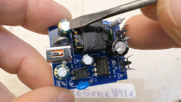
The second charger didn’t fare any better; although it didn’t overheat, that’s mainly because it shut itself off before it could deliver a fraction of its rated 1 amp output. The PCB construction was shoddy in the extreme, with a squiggly trace standing in for a proper fuse and a fraction of a millimeter separation between primary and secondary traces. The flyback transformer was a treat, too; who doesn’t want to rely on a whisper-thin layer of cheap lacquer to keep mains voltage out of your phone?

All in all, these designs are horrible, and we have to thank [DiodeGoneWild] for the nightmares we’ll have whenever we plug into one of these things from now on. On the other hand, this was a great introduction to switch-mode power supply designs, and what not to do with our own builds. Continue reading “Just How Dodgy Are Cheap USB Chargers Anyway?”

AC-DC Converter Is Reliable, Safe, And Efficient

When first starting an electronics project, it’s not uncommon to dive right in to getting the core parts of the project working. Breadboarding the project usually involves working with a benchtop power supply of some sort, but when it comes to finalizing the project the actual power supply is often glossed over. It’s not a glamorous part of a project or the part most of us want to be working with, but it’s critical to making sure projects don’t turn up with mysterious issues in the future. We can look to some others’ work to simplify this part of our projects, though, like this power supply from [hesam.moshiri].

The power supply is designed around a switch-mode topology known as a flyback converter. Flyback converters work by storing electrical energy in the magnetic field of a transformer when it is switched on, and then delivering that energy to the circuit when it is switched off. By manipulating the switching frequency and turns ratios of the transformer, the circuit can have an arbitrary output voltage. In this case, it is designed to take 220V AC and convert it to 8V DC. It uses a simplified controller chip to decrease complexity and parts count, maintains galvanic isolation for safety, and is built to be as stable as possible within its 24W power limitation to eliminate any potential issues downstream.

For anyone trying to track down electrical gremlins in a project, it’s not a bad idea to take a long look at the power supply first. Any noise or unwanted behavior here is likely to cause effects especially in projects involving sensors, ADC or DAC, or other low-voltage or sensitive components. The schematic and bill of materials are available for this one as well, so anyone’s next project could use this and even make slight adjustments to change the output voltage if needed. And, if this is your first introduction to switched-mode power supplies, check out this in-depth look at the similar buck converter circuit to better understand what’s going on behind the scenes on these devices.

Continue reading “AC-DC Converter Is Reliable, Safe, And Efficient”

Well-Protected USB Power Strip Makes It Easy To Plug In

When we get a new device these days, somewhere in the package is likely to be a wall-wart USB power supply. We look for a place to plug in the little switch-mode dongle, rearrange a few plugs in the mains power strip, and curse its designers for the overly cozy outlet spacing. And all the while that USB-A plug on the power supply cable taunts us with its neat, compact form factor. If only there were a USB power strip.

Unwilling to suffer such indignity any longer, [Scott M. Baker] took matters into his own hands and designed this USB power distribution system. We were surprised to hear that he was unable to find a commercial USB power strip, but even if he had, it likely wouldn’t have had the bells and whistles that he added to his. The circuit went through a couple of revs, but each was focused on protection of the connected USB devices. He included both overcurrent protection, in the form of an electronic fuse built around a TPS2421 hot-swap controller, and overvoltage protection using a crowbar circuit with the usual zener-SCR arrangement. There’s also a transient voltage suppression diode to keep any inductive spikes at bay. Interestingly, each USB outlet has all these protections – it’s not just one protected bus feeding a bunch of USB outlets in parallel, but individual modules with all the circuitry. The modules are gangable and live inside a laser-cut acrylic case. The video below shows the design and build process in some detail.

We have to say that we always learn a lot about circuit design from [Scott]’s projects. You may recall his custom Atari 2600 controller or his dual-port memory retro game console, both interesting and instructive builds in their own right.

Continue reading “Well-Protected USB Power Strip Makes It Easy To Plug In”

Fail Of The Week: Switched-mode PSU Camera Battery Replacement

We really wanted this week’s Fail to work. [Michael] wanted more juice for his Nikon D3100 camera. The idea he had was to replace the cells of the battery with a Buck converter and add leads for an external battery. This opens up the possibility of running from a wide range of voltage sources; an attractive prospect for devices using specialize batteries. Specifically, he wanted to swap out the stock 7.4V 1030 mAh battery and use an 18 Ah lead acid one instead.

The biggest hurdle to get over in a project like this one is the logic the camera uses to communicate with the battery. For this reason — and for the ease of hitting the right form factor — he scrapped an old battery pack to reuse the logic board and enclosure. His power supply is a free-formed circuit which fits nicely in the allotted space.

The circuit powers up, but only to about 6.4V. This isn’t enough to run the camera, which means this was just an expensive way for [Michael] to practice his soldering. After the jump you can read his recounting of the experience. You’ll also find a few of the build images, and the two hand-drawn schematics he used during development. His Dropbox has the entire collection of images.

Continue reading “Fail Of The Week: Switched-mode PSU Camera Battery Replacement”

Switched Mode Power Supply Repair Guide

switched_mode_power_supply_repaiir

[Erich] spotted a broken DVD recorder at a local amateur radio meeting and decided to see if he could restore it to working order. While he was fortunate enough that someone labeled it as having a bad power supply, things aren’t always that easy. He gives a broad explanation as to how switched mode power supplies work as well as discusses some of the reasons these devices tend to fail. He identifies a few common components and areas that one should check while diagnosing a non-functioning power supply. While obvious bulging capacitors are easily identifiable, he discusses the need for an ESR meter and uses a kit-built model to test capacitors that do not have any visual signs of damage. While some of his walkthrough might be basic knowledge for readers who have experience in recapping circuit boards, it serves as a nice guide for those who are new to the world of electronics troubleshooting and repair.

Make Switched-mode Power Supplies Do Your Bidding

[Ken] needed to supply 3.3 volts of regulated power. He started by using a linear voltage regulator but after a few calculations he discovered that 72% of what he put in was lost to heat. The solution to this is a switched-mode power supply. Rather than burn off energy through a voltage divider, an SMPS turns the power on and off very quickly to achieve the desired voltage.

A car charger-type USB regulator was chosen as [Ken’s] donor device. He figured that making adjustments to the resistors inside would affect the output voltage and he was right. He adjusted the potential divider and ended up with a steady 3.295V.

We asked him to share the schematic that he put together from studying the board and he came through. See that and get the link to the DC-DC converter datasheet after the break. Continue reading “Make Switched-mode Power Supplies Do Your Bidding”