Three Way LED Bulb Gives Up Its Secrets

You’ve probably seen three-way bulbs. You know, the ones that can go dim or bright with each turn of a switch. [Brian Dipert] wondered how the LED version of these works, and now that he tore one apart, you can find out, too. The old light bulbs were easy to figure out. They had two filaments, one brighter than the other. Switching on the first filament provided some light, and the second gave off more light. The final position lit both filaments at once for an even brighter light.

LED or filament, three-way bulbs have a special base. While a normal Edison-base bulb has the threaded part as the neutral and a center contact for the live wire, a three-way bulb has an extra hot contact ring between the threaded part and the center contact. Obviously, a compatible LED bulb will need this same interface, but will work differently inside.

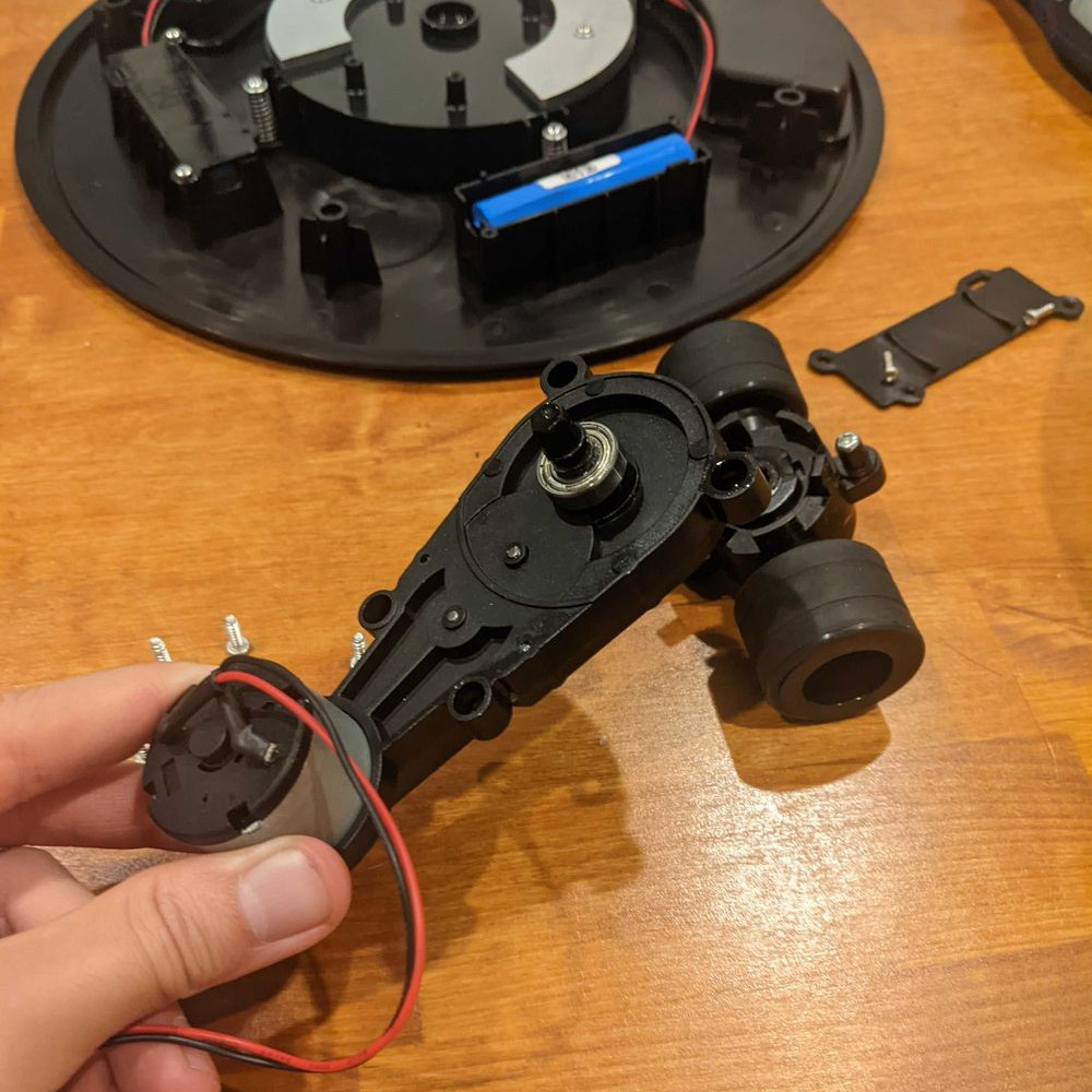
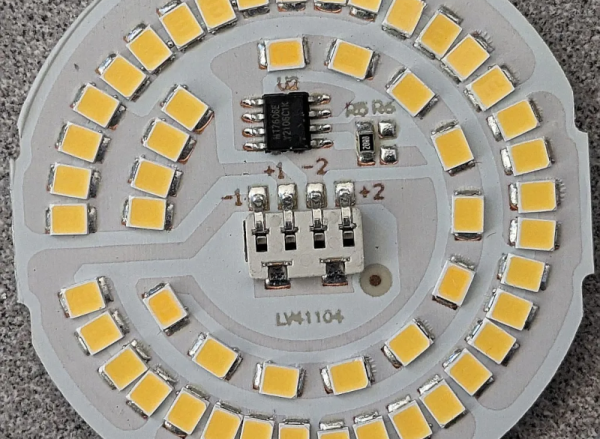
Inside the LED, [Brian] found two rings of LEDs that took the place of the filaments. He was able to identify all the ICs and devices on the board except one, an MT7712S. If you can read Mandarin, we think this is the datasheet for it.

We weren’t sure what [Brian] would find inside. After all, you could just sense which contacts had voltage and dim the LEDs using PWM. It probably wouldn’t take any less circuitry. LED lighting is everywhere these days, and maybe they don’t all work the same, but you have to admit, using two strings of LEDs is reasonably faithful to the old-fashioned bulbs.

Sometimes LED bulbs are different depending on where you buy them. We were promised LED bulbs would never burn out. Of course, they do, but you can usually scrounge some LEDs from them.

That Cheap USB Charger Could Be Costly

[Big Clive] picked up a keychain battery to charge his phone and found out that it was no bargain. Due to a wiring mistake, the unit was wired backward, delivering -5 V instead of 5 V. The good news is that it gave him an excuse to tear the thing open and see what was inside. You can see the video of the teardown below.

The PCB had the correct terminals marked G and 5 V, it’s just that the red wire for the USB connector was attached to G, and the black wire was connected to 5 V. Somewhat surprisingly, the overall circuit and PCB design was pretty good. It was simply a mistake in manufacturing and, of course, shows a complete lack of quality assurance testing.

The circuit was essentially right out of the data sheet, but it was faithfully reproduced. We should probably test anything like this before plugging it into a device, but we typically don’t. Does our phone protect against reverse polarity? Don’t know, and we don’t want to find out. [Clive] also noted that the battery capacity was overstated as well, but frankly, we’ve come to expect that with cheap gadgets like this.

This isn’t, of course, the first phone charger teardown we’ve seen. This probably isn’t as deadly as the USB killer, but we still wouldn’t want to risk it.

Continue reading “That Cheap USB Charger Could Be Costly”

German Air Force Surplus Teardown

It isn’t clear to us how [mrsylvain59] came into possession of a late-model piece of military gear from the German airforce, but we enjoyed watching the teardown below anyway. According to the documentation, the thing has a huge price tag, although we all know that the military usually pays top dollar for various reasons, so we are guessing the cost of the parts is quite a bit less than the price tag.

We don’t think [mrsylvain59] was sure what the amplifier (verstärker is German for amplifier) does. However, we recognized it as an avionics box from a UH-1 helicopter. We aren’t sure of its exact function, but it is classified under “Automatic Pilot Mechanisms and Airborne Gyro Components.”

Continue reading “German Air Force Surplus Teardown”

Watch Sony Engineers Tear Down Sony’s VR Hardware

Teardowns are great because they let us peek not only at a product’s components, but also gain insight into the design decisions and implementations of hardware. For teardowns, we’re used to waiting until enthusiasts and enterprising hackers create them, so it came as a bit of a surprise to see Sony themselves share detailed teardowns of the new PlayStation VR2 hardware. (If you prefer the direct video links, Engineer [Takamasa Araki] shows off the headset, and [Takeshi Igarashi] does the same for the controllers.)

The “adaptive trigger” module responsible for the unique feedback.

One particularly intriguing detail is the custom tool [Araki] uses to hold the headset at various stages of the disassembly, which is visible in the picture above. It looks 3D-printed and carefully designed, and while we’re not sure what it’s made from, it does have a strong resemblance to certain high-temperature SLA resins. Those cure into hard, glassy, off-yellow translucent prints like what we see here.

As for the controller, we get a good look at a deeply interesting assembly Sony calls their “adaptive trigger”. What’s so clever about it? Not only can it cause the user to feel a variable amount of resistance when pulling the trigger, it can even actively push back against one’s finger, and the way it works is simple and effective. It is pretty much the same as what is in the PS5 controller, so to find out all about how it works, check out our PS5 controller teardown coverage.

The headset and controller teardown videos are embedded just below. Did anything in them catch your interest? Know of any other companies doing their own teardowns? Let us know in the comments!

Continue reading “Watch Sony Engineers Tear Down Sony’s VR Hardware”

Anatomy Of A Fake CO2 Sensor

The pandemic brought with it a need to maintain adequate ventilation in enclosed spaces, and thus, there’s been considerable interest in inexpensive C02 monitors. Unfortunately, there are unscrupulous actors out there that have seen this as a chance to make a quick profit.

Recently [bigclivedotcom] got one such low-cost CO2 sensor on his bench for a teardown, and confirms that it’s a fake. But in doing so he reveals a fascinating story of design decisions good and bad, from something which could almost have been a useful product.

Behind the slick color display is a PCB with an unidentified microcontroller, power supply circuitry, a DHT11 environmental sensor, and a further small module which purports to be the CO2 sensor. He quickly demonstrates with a SodaStream that it doesn’t respond to CO2 at all, and through further tests is able to identify it as an alcohol sensor.

Beyond the alcohol sensor he analyses the PSU circuitry. It has a place for a battery protection chip but it’s not fitted, and an error in the regulator circuitry leads to a slow drain of the unprotected cell. Most oddly there’s an entire 5 volt switching regulator circuit that’s fitted but unused, being in place to support a missing infra-red module. Finally the screen is an application-specific LCD part.

It’s clear some effort went in to the design of this unit, and we can’t help wondering whether it could have started life as a design for a higher-spec genuine unit. But as [Clive] says, it’s a party detector, and of little more use than as a project case and battery.

Need more dubious instrumentation? How about a magnetic field tester?

Continue reading “Anatomy Of A Fake CO2 Sensor”

Seriously, Don’t Buy This Mopping Robot

The original Roomba robotic vacuum cleaner led to loads of clones and lookalikes over the years, and one of them is the ALEE mopping “robot”. [Raymond] tears it down and reveals what’s inside. Turns out it contains mostly regret! Although it does host some design cleverness in its own way.

Technically the ALEE, which cost [Raymond] a cool $85 USD, is not a robot since it has no sensors. And unless a dragging a wet cloth pad kept moist by a crude drip reservoir counts as “mopping”, it’s not much of a mop, either.

This one-motor unit (and tiny battery) is responsible for both motion and direction control. There are no sensors.

There is one interesting aspect to this thing, and it’s to do with the drive system and direction control. The whole thing is driven by a single motor, and not a very powerful one. The center of the robot has a pair of wheels that are both driven at the same rate and speed, and the wheel assembly can pivot around its axis. That’s about it. There are not even any bump sensors of any kind.

So how does this thing move, let alone change direction to (poorly) emulate an original Roomba-like crisscross pattern? The control board appears to have one job: if the motor stalls, reverse direction. That, combined with the fact that the drive unit can pivot and the enclosure is dragging a wet rag, appears to be all the chaos that’s needed to turn bonking into a wall into an undefined direction change.

It’s not great performance, but it sure is some impressive cost-cutting. You can see it bonk around unimpressively in a short video, embedded below the page break.

Just to be clear, [Raymond] knows perfectly well what he’s in for when he obtains cheap tech items from overseas retailers for teardowns. The ALEE does have some mildly interesting secrets to share, but overall, it really wasn’t worth it. Sometimes cheap tech has hacker potential, but there’s no such potential here. Seriously, don’t buy this thing.

Continue reading “Seriously, Don’t Buy This Mopping Robot”

Mini Cheetah Clone Teardown, By None Other Than Original Designer

[Ben Katz] designed the original MIT Mini Cheetah robot, which easily captured attention and imagination with its decidedly un-robotic movements and backflips. Not long after [Ben]’s masters thesis went online, clones of the actuators started to show up at overseas sellers, and a few months after that, clones of the whole robot. [Ben] recently had the opportunity to disassemble just such a clone by Dogotix and see what was inside.

Mini sheep, meet mini cheetah.

Amusingly, one of the first things he noticed is that the “feet” are still just off-the-shelf squash balls, same as his original mini cheetah design. As for the rest of the leg, inside is a belt that goes past some tensioners, connecting the knee joint to an actuator in the shoulder.

As one may expect, these parts are subject to a fair bit of stress, so they have to be sturdy. This design allows for slender yet strong legs without putting an actuator in the knee joint, and you may recall we’ve seen a similar robot gain the ability to stand with the addition of a rigid brace.

It’s interesting to read [Ben]’s thoughts as he disassembles and photographs the unit, and you’ll have to read his post to catch them all. But in the meantime, why not take a moment to see how a neighbor’s curious sheep react to the robot in the video embedded below? The robot botches a backflip due to a low battery, but the sheep seem suitably impressed anyway.

Continue reading “Mini Cheetah Clone Teardown, By None Other Than Original Designer”