If predictions hold steady, nearly half of the United States will be covered in snow by the time this post goes live, with the Northeast potentially getting buried under more than 18 inches. According to the National Weather Service, the “unusually expansive and long-duration winter storm will bring heavy snow from the central U.S. across the Midwest, Ohio Valley, and through the northeastern U.S. for the remainder of the weekend into Monday.” If that sounds like a fun snow day, they go on to clarify that “crippling to locally catastrophic impacts can be expected”, so keep that in mind. Hopefully you didn’t have any travel plans, as CNBC reported that more than 13,000 flights were canceled as of Friday night. If you’re looking to keep up with the latest developments, we recently came across StormWatch (GitHub repo), a slick open source weather dashboard that’s written entirely in HTML. Stay safe out there, hackers.
Speaking of travel, did you hear about Sebastian Heyneman’s Bogus Journey to Davos? The entrepreneur (or “Tech Bro” to use the parlance of our times) was in town to woo investors attending the World Economic Forum, but ended up spending the night in a Swiss jail cell because the authorities thought he might be a spy. Apparently he had brought along a prototype for the anti-fraud device he was hawking, and mistakenly left it laying on a table while he was rubbing shoulders. It was picked up by security guards and found to contain a very spooky ESP32 development board, so naturally he was whisked off for interrogation. A search of his hotel room uncovered more suspicious equipment, including an electric screwdriver and a soldering iron. Imagine if a child had gotten their hands on them?
While we typically encourage hackers to make their own tools or machines when practical, x-ray machines don’t usually make that list. Despite the risk of radiation, [William Osman] has done just that and built a homemade x-ray machine. After receiving an eye-watering medical bill, [William] resolves to make his own x-ray machine in the hopes of avoiding future bills. Thanks to his insurance, the total owed was smaller but still ridiculous to those who live in single-payer health care countries, but it got William thinking. What if he could make an x-ray machine to do cheap x-rays?
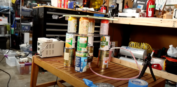
Armed with a cheap high voltage DC power supply he acquired from an online auction house, he started to power up his x-ray vacuum tube. A smaller power supply energizes the cathode and forms an electron beam. Then the high voltage (30-150kv) is applied as a tube voltage, accelerating the electrons into x-rays. Safety measures are taken somewhat haphazardly with Geiger counters and lead sheets. With a finger bone cast in ballistic shell [William] made his first x-ray with a long exposure on a DSLR. The next items to go in the x-ray “chamber” were a phone and a hand. The results were actually pretty decent and you can clearly see the bones.
We’ve seen homemade X-Ray machines here at Hackaday before, but not one that is constructed perhaps so haphazardly — his approach makes this obvious: don’t try this at home. Video after the break.
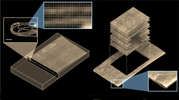
Over recent years we’ve been treated to a series of fascinating advances in the world of x-ray imaging, as researchers have developed their x-ray microtomography techniques and equipment to the point at which they can probe and then computationally reconstruct written material within objects such as letters or scrolls in museum collections whose value or fragility means they can’t be opened and read conventionally. There is more to this challenge than simply extracting the writing though, in addition to detecting the ink the researchers also have to unpick the structure of whatever it was written upon. A particular challenge comes from letterpackets, the art of folding a letter into its own envelope, and a newly-published Nature Communications paper details work from a team of academics in the USA, the UK, and the Netherlands in tackling it.
Letterpackets were more than a practical method of packaging a missive for the mail, they also had a security function often called Letterlocking. A packet would be folded in such a way as to ensure it was impossible to open without tearing or otherwise damaging the paper, and their structure is of especial interest to historians. The researchers had a unique resource with which to work; the Brienne collection is a trunk full of undeliverable mail amassed by a 17th century postmaster couple in Den Haag in the Netherlands, and now in the possession of the Beeld en Geluid museum in that city. In it were a cache of letters including 577 never-opened letterpackets, and the x-ray technique promised a means to analyse these without compromising them.
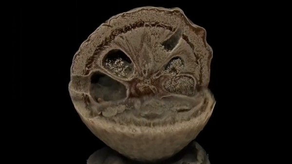
A letter imaged using the technique.
The researchers have developed an entirely computational technique for the virtual unfolding process. Starting with a 3D volumetric x-ray scan of the unopened packet they then identify the various layers of paper and the bright spots which denote the ink. Their algorithm has to cope with areas in which two or more layers are tightly in contact, for example when multiple levels are folded, and then unpick the resulting 3-dimensional mesh into a 2-dimensional sheet. Their process for mapping the crease pattern involves applying a colour map representing the mean curve radius at a given point. The final section of the paper looks at the multiple different methods of letterlocking, and attempts to categorise them all including a security rating for each. It’s evident that this could be a highly personalised process, indeed they give as an example a letter from Mary Queen of Scots that used an intricate spiral folding technique to identify its sender.
It’s clear that this technique will reveal many more fascinating historical documents as it is both refined and extended across the many more collections of further artefacts that have lain waiting for it. As they say, individual letters do not necessarily contain earth-shattering historical discoveries, but taken together they shed an important light on the social history of past centuries.
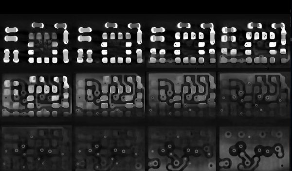
At risk of getting any ASMR buffs who might be reading cranky because there’s no audio, [Chris], or [@no1089] on Twitter, has gifted us with this visually stunning scan of his Maxim MAX86160 in-ear heart monitor mounted on a rigidflex PCB. You can take a look, in the video below the break.
If you’re wondering why anyone would scan a board, other than boredom, know that it’s actually quite common. X-Ray machines are commonly used as a quick, passive way to check a board that’s fresh off the production line. These aren’t the X-Rays like those of broken bones you’re (hopefully not too) used to seeing though, they’re Computed Tomography scans (CT scans, CAT scans), in effect just 3D X-Rays.
For electronics manufacturers and assemblers, CT scans are incredibly useful because they provide a non-destructive way to check for errors. For example, how do you know if that middle BGA pin is actually soldered correctly? You could run a functional test and make sure everything is working (at least, everything you check), but that takes time. The longer it takes to validate, the higher the manufacturing cost. In manager speak: “cost bad. Fast good.”
It’s also common to use a CT scan to create a full 3D model of a board. This makes it easy to check every little detail, especially the ones that are visually obscured by surface mount devices or critical signal paths that are buried under board layers.
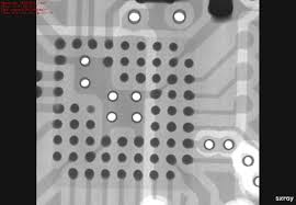
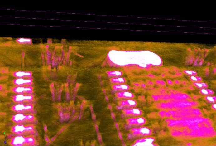
Highlight of solder joints on small-outline integrated circuit (SOIC) to a PCB’s pads.
But we know you really want more of this video, but better. And we’ve got the goods. For the chill folk among you, here’s a 55-minute version without all the CT scan info cluttering the screen. For those of you currently blasting eDM in your headphones, here’s a 30 second clip of it looping at ~5x speed. Eat your heart out:
Once you’ve built your own X-ray machine to take 2D images of the insides of stuff, there’s really only one logical next step: building your own computed tomography (CT) scanner to get 3D reconstructions instead. That’s exactly what [Fran Piernas] has done, and documented over on hackaday.io. While the original X-ray machine build dealt with scary hardware stuff such as high voltage and ionizing radiation, this time it’s the turn of scary mathematics like inverse radon transforms.
The original build, which we wrote about in December, uses a commercial dental X-ray tube and a home-made 65 kV power supply to send X-rays through objects. Transmitted X-rays are viewed using an intensifying screen that converts the rays to visible light. The result is a 2D image similar to that we’re all familiar with.
To create a 3D reconstruction of an object, you need a number of X-ray images taken from different angles. If you’ve ever been unlucky enough to need a medical CT scan, you’ll remember staying motionless in the tunnel while the X-ray apparatus rotated around you. In this build, [Fran] rotates the object instead, using a motor that may have once been part of a microwave oven (one of those “mystery motors” we all have laying around). The required sequence of images is simply obtained by recording video of the X-ray screen while the motor rotates the object.
We all know CERN as that cool place where physicists play with massive, superconducting rings to smash atoms and subatomic particles to uncover secrets of matter in the Universe. To achieve this aim, they need to do a ton of research in other areas, such as development of special particle detectors.
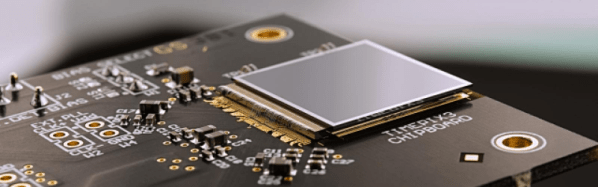
While such developments are essential to the core research needs of the Centre, they also lead to spinoff applications for the benefit of society at large. One such outcome has been the Medipix Collaborations – a family of read-out chips for particle imaging and detection that can count single photons, allowing X-rays and gamma rays to be converted to electrical signals. It may not be possible for us hackers to get our hands on these esoteric sensors, but these devices are pretty interesting and deserve a closer look. Medipix sensors work like a camera, detecting and counting each individual particle hitting the pixels when its electronic shutter is open. This enables high-resolution, high-contrast, noise hit free images – making it unique for imaging applications.
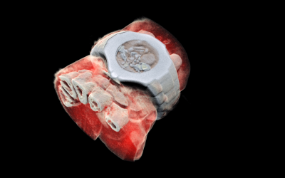
Some months back, CERN announced the first 3D color X-ray of a human made possible using the Medipix devices. The result is a high-resolution, 3D, color image of not just living structures like bones, muscular tissues and vessels, but metal objects too like the wrist watch, seen in the accompanying photograph. The Medipix sensors have been in development since the 1990’s and are presently in their 4th “generation”. Each chip consists of a top semiconducting sensor array, made from gallium arsenide or cadmium telluride. The charge collected by each pixel is transported to the CMOS ASIC electronics via “bump bonds”. The integration is vertical, with each sensing pixel connected via the bump bond to an analog section followed by a digital processing layer. Earlier versions were limited, by technology, in their tiling ability for creating larger matrices of multiple sensors. They could be abutted on three sides only, with the fourth being used for on-chip peripheral logic and wire-bond pads that permit electronic read-out. The latest Medipix4 Collaboration, still under some development, eliminates this short coming. Through-silicon-via (TSV) technology provides the possibility of reading the chips through copper-filled holes that bring the signals from the front side of the chip to its rear. All communication with the pixel matrix flows through the rear of the chip – the peripheral logic and control elements are integrated inside the pixel matrix.
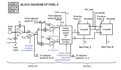
The Analog front end consists of a pre-amplifier followed by a window discriminator which has upper and lower threshold levels. The discriminator has four bits for threshold adjustment as well as polarity sensing. This allows the capture window to be precisely set. The rest of the digital electronics – multiplexers, shift registers, shutter and logic control – helps extract the data.
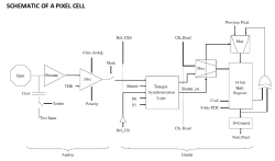
Further development of the Medipix (Tech Brief, PDF) devices led to a separate version called Timepix (Tech Brief, PDF). These new devices, besides being able to count photons, are capable of two additional modes. The first mode records “Time-Over-Threshold”, providing rough analog information about the energy of the photon. It does this by counting clock pulses for the duration when the signal stays above the discrimination levels. The other mode, “Time of Arrival”, measures arrival time of the first particle to impinge on the pixel. The counters record time between a trigger and detection of radiation quanta with energy above the discrimination level, allowing time-of-flight applications in imaging.
Medipix3 pixel schematic
Timepix2 pixel schematic
Besides medical imaging, the devices have applications in space, material analysis, education and of course, high energy physics. Hopefully, in a few years, hackers will lay their hands on these interesting devices and we can get to know them better. At the moment, the Medipix website has some more details and data sheets if you would like to dig deeper. For an overview on the development of such single photon detectors, check out this presentation from CERN – “Single X-Ray Photon Counting Systems: Existing Systems, Systems Under Development And Future Trends” (PDF).
David Mills is as a research scientist at the cutting edge of medical imaging. His work doesn’t involve the scanners you might find yourself being thrust into in a hospital should you be unfortunate enough to injure yourself. He’s working with a higher grade of equipment, he pushes the boundaries of the art with much smaller, very high resolution CT scanners for research at a university dental school.
He’s also a friend of Hackaday and we were excited for his talk on interesting uses for CT scanners at EMF Camp this summer. David takes us into that world with history of these tools, a few examples of teeth and bone scans, and then delves into some of the more unusual applications to which his very specialist equipment has been applied. Join me after the break as we cover the lesser known ways to put x-ray technology to work.


 Some months back, CERN announced
 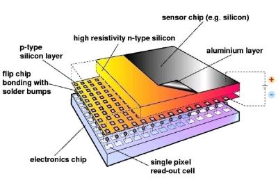 The Analog front end consists of a pre-amplifier followed by a window discriminator which has upper and lower threshold levels. The discriminator has four bits for threshold adjustment as well as polarity sensing. This allows the capture window to be precisely set. The rest of the digital electronics – multiplexers, shift registers, shutter and logic control – helps extract the data.