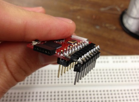
[John] wrote in with a solution to a prototyping issue that has vexed us for quite some time. Above you can see the DIP friendly solution for dual-row pin headers which he came up with. With just a bit of easy soldering he now has a breadboard friendly device for prototyping.
He starts by soldering a dual row pin header on the board, then clips off all of the legs on the outside row. The row of legs that remain are then inserted into one side of the trench on his breadboard. The other side of the trench has a single row pin header, and he solders them to the outer row on the breakout board using another single pin header aligned horizontally. This isn’t a 100% convenient solution, as it’s still pretty hard to get your jumper wires in the breadboard on the side covered by the breakout board. But if you plan in advance you can place your wires first, then plug in the development board.
Here [John] is working with TI’s eZ430-RF2500 board. We’d like to go back and remove the dual pin socket we soldered on our eZ430-F2013, replacing it with this style of pins.

