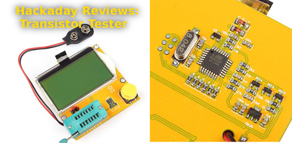
Amazon has been getting creepier and creepier lately with their recommendations. Every time I log in, I’m presented with a list of new Blinky LEDs, Raspberry Pi accessories, Arduino shields, and the like. It’s as if they know me. Their customer database paid off when it recommended a $22 transistor / component tester. I’ve been seeing those testers around quite a bit lately. Curiosity got the better of me and my mouse found its way to the “Buy it now with one click” button. Two days later I had a “SainSmart Mega328 Transistor Tester Diode Triode Capacitance ESR Meter MOS/PNP/NPN L/C/R” in my hands.
I’m going to get the obvious out of the way. This thing is built cheap – as cheap as the factories can make it. My particular unit arrived with the LCD flapping in the breeze, hanging on by its flex cable. Fitting the LCD back into the acrylic backlight frame revealed a slightly worrisome twist in that same flex. Thankfully nothing was actually damaged, though I do want to give the flex cable some protection in the future. More on that later. The circuitry was open for all the world to see on the bottom of the tester. The heart of the unit is an ATmega328. Supporting it are a few transistors and a handful of passives.
I didn’t have huge expectations for the tester, but I hoped it would at least power up. Hooking up a 9 volt battery and pressing the magic button brought the tester to life. Since I didn’t have anything in the socket, it quickly lit up and displayed its maker information – “91make.taobao.com”, and “By Efan & HaoQixin”, then it informed me that I had “No, unknown, or damaged part”.
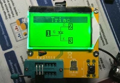
I had a few resistors lying around the bench (doesn’t everyone?) so I put one in. The tester read it as 9881 ohms. Sure enough, it was a 10K 5% resistor. Capacitors – ceramic disc, electrolytic, and surface mount all worked as well. The tester even provided ESR values. The real test would be a transistor. I pulled an old 2N2222 in a TO-18 metal can, and popped it in the tester. The damn thing worked – it showed the schematic symbol for an NPN transistor with Collector, Base, and Emitter connected to Pins 1,2,and 3 respectively. Flipping the pins around and re-testing worked as well. The tester showed hFe as 216, and forward voltage as 692 mV, both reasonable numbers for a 2N2222.
 The tester worked surprisingly well – it was able to correctly identify BJTs, FETs, even esoteric parts. The only thing it balked on was a linear voltage regulator, which showed up as two diodes. Regulators are a bit more than a simple device though, so I can’t blame the tester there. The values returned were all reasonable as well. While I don’t have a calibrated lab to check against, the numbers lined up with my Fluke meter.
So what exactly is driving this little tester? There are about 20 versions of it on the market, all of them from China. 91make is a seller on taobao.com, often referred to as “China’s ebay.” 91make’s front page features no less than 7 versions of the transistor tester, with various cases and LCDs. Some digging turned up the history on this device. It turns out the transistor tester is an open source hardware project (translated) originally created by [Markus Frejek], and built upon by [Karl-Heinz Kubbeler] and a number of others. The Subversion repository for the project shows it is quite active, with the most recent check-in only a few hours ago. The project is also well documented. The English PDF is 103 pages, explaining theory of operation, the circuit itself, and the software. The document even explains some of the shortcomings of the Chinese versions of the tester, including using a zener diode where the original schematic calls for a precision 2.5V reference. Yes, it will work, but it won’t be as accurate as the original.
The devs also don’t officially support the clones which I can understand, considering the quality and changes in design each manufacturer is baking in to their own version. There is a huge thread on the EEVblog forum covering these testers. Some can be modified to be closer to the official version. In fact, with an ISP tool the intrepid hacker can update the firmware to the current rev from [Karl-Heinz’s] repository.
So the final verdict on this tester is that it is a thumbs up with a small caveat. These testers are built down to a cost (and that cost is as close to zero as possible). They’re great for sorting parts, but they’re no substitute for a higher quality measuring device. I’d also love to see a version that supports the original developers.
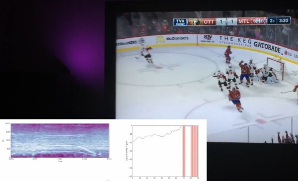
 [François] started off by listening to the audio of some recorded games. Whenever a goal is scored, the commentator yells out and the goal horn is sounded. This makes it pretty obvious to the listener that a goal has been scored, but detecting it with a computer is a bit harder. [François] also wanted to detect when his home team scored a goal, but not when the opposing team scored, making the problem even more complicated!
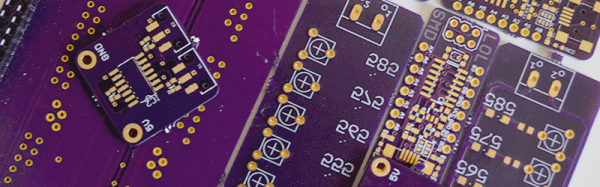
 For each of the last four weeks we’ve awarded prize packages to three projects just for submitting ideas. Now it’s time to crank up the rewards. Over the next 17 weeks we will give away $50,000 in prizes. We’re kicking off the week by giving $50
  To give yourself the best chance at winning, publish a new project log this week that outlines the PCB work your want to do for the entry. We’ll be looking for those as we judge the prizes that are most ready to begin (or advance) their hardware build.