Ask Hackaday: Is The ESP8266 5V Tolerant?

The ESP8266 is the reigning WiFi wonderchip, quickly securing its reputation as the go-to platform for an entire ecosystem of wireless devices. There’s nothing that beats the ESP8266 on a capability vs. price comparison, and this tiny chip is even finding its way into commercial products. It’s also a fantastic device for the hardware tinkerer, leading to thousands of homebrew projects revolving around this tiny magical device.

In every technical document, summary, and description of the ESP8266, the ESP8266 is said to be a 3.3V part. While we’re well into the age of 3.3V logic, there are still an incredible number of boards and hardware that still operate using 5V logic. Over on the Hackaday.io stack, [Radomir] is questioning this basic assumption. He’s wondering if the ESP8266 is 5V tolerant after all. If it is, great. We don’t need level converters, and interfacing the ESP to USB TTL serial adapters becomes much easier. Yes, you’ll still need to use a regulator if the rest of your project is running at 5V, but if the pins are 5V tolerant, interfacing the ESP8266 with a variety of hardware becomes very easy.

[Radomir]’s evidence for the possibility of 5V tolerant inputs comes from a slight difference in the official datasheet from Espressif, and the datasheet translated by the community before Espressif realized how many of these chips they were going to sell.

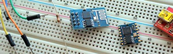
The best evidence of 5V tolerant pins might come from real-world experience — if you can drive a pin with 5V for months on end without it failing, there might be something to this claim. It’s not definitive, though; just because a device will work with 5V input pins for a few months doesn’t mean it won’t fail in the future. So far a few people have spoken up and presented ESPs directly connected to the 5V pin of an Arduino that still work after months of service. If this is evidence of 5V tolerant design or simply luck is another matter entirely.

While the official datasheet from Espressif lists a maximum VIH of 3.3V, maximum specs rarely are true maximums — you can always push a part harder without things flying apart at the seams. Unfortunately, unless we hear something from the engineers at Espressif, we won’t know if the ESP8266 was designed to be 5V tolerant, if it can handle 5V signals reliably, or if 5V signals are a really good way to kill a chip eventually.

Lucky for us — and this brings us to the entire point of an Ask Hackaday column — a few Espressif engineers read Hackaday. They’re welcome to pseudonymously chime in below along with the rest of the peanut gallery. Failing that, the ESP8266 has been decapped; are there any die inspection wizards who can back up a claim of 5V tolerance for the GPIO? We’d also be interested in hearing any ideas for stress testing pin tolerance.

Amazing SDR Built By 16 Year Old

[Lukas] started his epic SDR-from-scratch build when he was 16. Projects like this aren’t completed overnight. (He’s now 18. We’re impressed.)

The project itself is a Software-Defined Radio built on top of the 12-bit Analog Devices AD9364 transceiver IC. A big fat FPGA takes the data and runs it off to a USB 3.0 interface, which is necessary for the amount of data this thing will be producing — he’s got it receiving 56 MHz of bandwidth. In short, this is an SDR peripheral that’s in the big leagues.

After two years of work and (only!) three revision, [Lukas] got the thing working. Read his writeup for the blow-by-blow account. In the end, a 6-layer board was necessary for the routing to get the full speed out of the clocking, and he discovered the reason that you use exactly the specified bias resistors — the expensive ADC chip gets very hot. But he didn’t give up, and in the end he pulled off a project of immense complexity. In his own words:

I have discovered that taking on large projects, even when not knowing how to tackle problems that might arise, is a very effective way of learning for me. It’s just important to be persistent, as I’ve seen that almost any problem can be solved on your own — which is incredibly rewarding — even if you get stuck and seem to not make progress for a while.

[Lukas] is now working on the software. He’s already got a hacked osmocom driver working, so it plays nice with GNURadio.

Of course, there are tons of ways to get into SDR without building your own from scratch, but we applaud [Lukas] for going the hard way. If you’re tempted to follow in his footsteps, have a look at [Michael Ossmann]’s great talk on making the RF design process as tractable as possible.

Power Log Splitting: Trying (and Sometimes Failing) To Build A Better Ax

Wood. Humans have burned it for to heat their homes for thousands of years. It’s truly a renewable source of energy. While it may not be the most efficient or green method to warm a space, it definitely gets the job done. Many homes still have a fireplace or wood burning stove for supplemental heat. For those in colder climates, wood is more than just supplemental, it’s needed simply for survival.

Splitting maul by Chmee2 via Wikipedia

The problem with firewood is that it doesn’t come ready to burn. Perfect fireplace sized chunks don’t grow on trees after all. The trees have to be cut up into logs. The logs must be split. The split wood then needs to dry for 6 months or so.

Anyone who’s spent time manually splitting wood can tell you it’s back breaking work. Swinging an 8 pound maul for a few hours will leave your hands numb and your shoulders aching. It’s the kind of work that leaves the mind free to wander a bit. The hacker’s mind will always wander toward a better way to get the job done. Curiously we haven’t seen too many log splitting hacks here on the blog. [KH4] built an incredible cross bladed axe back in 2015, but that’s about it.

Continue reading “Power Log Splitting: Trying (and Sometimes Failing) To Build A Better Ax”

Computer-Designed Portraits, Knit By Hand!

Artist [Petros Vrellis] has done something that we’ve never seen before: his piece “A New Way to Knit” lives up to its name. What he’s done is to take the traditional circular loom, some black thread, and toss some computing at it. And then he loops the string around and around and around.

a-new-way-to-knit-175653201mp4-shot0009_thumbnail

The end result of following the computer’s instructions is a greyscale portrait. Where few black strings overlap, it’s light, and where more overlap, it’s darker. That’s the whole gimmick, but the effect is awesome. As you zoom in and out, it goes from a recognizable face to a tangle of wires and back. Check out his video embedded below.

Continue reading “Computer-Designed Portraits, Knit By Hand!”

All-terrain Hoverboard Junk Pile Build

If you’re anything like us, chances are pretty good you’ve got at least one underused piece of fitness gear cluttering up your place. Rather than admit defeat on that New Year’s Resolution purchase, why not harvest the guts and build an all-terrain hoverboard for a little outdoor fun?

The fitness machine in question for [MakeItExtreme]’s build was a discarded Crazy Fit vibration platform. We’re not sure we see the fitness benefits of the original machine, but there’s no doubt it yielded plenty of goodies. The motor and drive belt look stout, and the control board eventually made it into the hoverboard too. The custom steel frame was fabricated using some of [MakeItExtreme]’s DIY tools, which is what we’re used to seeing them build — check out their sand blaster and spot welder for examples. A couple of knobby tires in the center of the board let the rider balance (there’s no gyro in this version) and power is provided by a couple of 12 volt AGM batteries. Sadly, the motor was a line voltage unit, so an inverter was needed. But it was the only part that had to be purchased, making this a pretty complete junk pile build.

See the video after the break for build details and a few test rides. Looks like it can do 20 mph or so – pretty impressive.

Continue reading “All-terrain Hoverboard Junk Pile Build”

Hackaday Prize Entry: A Suite Of Lab Instruments

For their Hackaday Prize entry, [Jithin], [Praveen], [Varunbluboy], and [Georges] are working on SEELablet, a device that will equip budding citizen scientists with control and measurement equipment.

One of the best ‘all-in-one’ lab devices is National Instruments’ VirtualBench, a device that’s an oscilloscope, logic analyzer, function generator, multimeter, and power supply, all crammed into one box. There’s a lot you can do with a device like this, but as you would expect, the name-brand version of this isn’t meant for middle school students.

In an effort to bring the cost of an all-in-one lab tool down to a price mere mortals can afford, the team behind the SEELablet have combined a single board computer with the capability of an oscilloscope, frequency counter, logic analyser, waveform generator, and a programmable power supply.

This has been a multi-year project for the team, beginning with a Python-powered instrumentation tool, and later a device running this code that’s also a versatile lab tool. If the latest iteration of the project turns out to be all it promises, we can’t wait to see the data this box will produce. There’s a lot you can measure in a fully stocked electronics lab, and this project makes the whole setup much easier to obtain.

FPGA Drives Old Laptop Screen

Every year, new models of laptops arrive on the shelves. This means that old laptops usually end up in landfills, which isn’t exactly ideal. If you don’t want to waste an old or obsolete laptop, though, there’s a way to reuse at least the screen out of one. Simply grab an FPGA off the shelf and get to work.

[Martin] shows us all how to perform this feat on our own, and goes into great detail about how all of the electronics involved work. Once everything was disassembled and the FPGA was wired up, it took him a substantial amount of time just to turn the display on. From there it was all downhill: [Martin] can now get any pattern to show up on the screen, within reason. The only limit to his display now seems to be the lack of external RAM. He currently uses the setup to drive an impressive-looking clock.

This is a big step from days passed where it was next to impossible to repurpose a laptop screen. Eventually someone discovered a way to drive these displays, and now there are cheap electronics from China that can usually get a screen like this running. It’s impressive to see it done from scratch, though, and the amount of detail in the videos are a great way to understand how everything is working.

Continue reading “FPGA Drives Old Laptop Screen”