Roll Your Own Arduino PWM

Most projects are built on abstractions. After all, few of us can create our own wire, our own transistors, or our own integrated circuits. A few months ago, [Julian Ilett] found a problem using the Arduino library for PWM. Recently, he revisited the issue and used his own PWM code to fix the problem. You can watch the video below.

Of course, neither the Arduino library nor [Julian’s] code is actually producing PWM. The Atmel CPU’s hardware is doing the work. The Arduino library gives you a wrapper called analogWrite — especially handy if you are not using an Atmel CPU where the same abstraction will do the same work. The issue arose when [Julian] broke the abstraction to invert the PWM output.

Continue reading “Roll Your Own Arduino PWM”

Conductive Concrete Confounds Circuitry

There’s a fairly good chance you’ve never tried to embed electronics into a chunk of concrete. Truth be told, before this one arrived to us via the tip line, the thought had never even occurred to us. After all, the conditions electronic components would have to endure during the pouring and curing process sound like a perfect storm of terrible: wet, alkaline, and with a bunch of pulverized minerals thrown in for good measure.

But as it turns out, the biggest issue with embedding electronics into concrete is something that most people aren’t even aware of: concrete is conductive. Not very conductive, mind you, but enough to cause problems. This is exactly where [Adam Kumpf] of Makefast Workshop found himself while working on a concrete enclosure for a color-changing barometer called LightNudge.

While putting a printed circuit board in the concrete was clearly not workable, [Adam] was hoping to simplify manufacturing of the device by embedding the DC power jack and capacitive touch sensor into the concrete itself. Unfortunately, [Adam] found that there was a resistance of about 200k Ohm between the touch sensor and the power jack; more than enough to mess with the sensitive measurements required for the touch sensor to function.

Even worse, the resistance of the concrete was found to change over time as the curing process continued, which can stretch out for weeks. With no reliable way to calibrate out the concrete’s internal conductivity, [Adam] needed a way to isolate his electronic components from the concrete itself.

Through trial and error, [Adam] eventually found a cheap method: dipping his sensor pad and wire into an acrylic enamel coating from the hardware store. It takes 24 hours to fully cure, and two coats to be sure no metal is exposed, but at least it’s an easy fix.

While the tip about concrete’s latent conductivity is interesting enough on its own, [Adam] also gives plenty of information about casting concrete parts which may be a useful bit of knowledge to store away for later. We have to admit, the final result is certainly much slicker than we would have expected.

This is the first one we’ve come across that’s embedded in concrete, but we’ve got no shortage of other capacitive touch projects if you’d like to get inspired.

UV Light Box Cures Both Sides Of A PCB

[GiorgiQ] needed a UV light to cure the etch resist on his printed circuit boards, and what better way to accomplish this than to build the perfect UV light box himself? The box consists of a custom PCB (of course) featuring a pair of 12V relays tripping quad 9×12 matrices of 400nm UV LEDs, with a total of 432 diodes in use — not to mention resistors to protect the LEDs. All of it is run by an Arduino Nano.

The enclosure is made out of 12mm MDF and 3mm cast acrylic, and the circuit board fits into a tray sliding on drawer sliders, allowing a resist-covered board to be placed in a carrier and slid back in.

DIY light boxes mostly don’t look as slick as [GiorgiQ]’s, but they’re a fairly common project. This one also uses 9×12 matrices of UV LEDs, while a distinctly simpler project involves making a UV exposure box out of fluorescent lights.


Open Source Underwater Glider Wins 2017 Hackaday Prize

The Open Source Underwater Glider has just been named the Grand Prize winner of the 2017 Hackaday Prize. As the top winner of the Hackaday Prize, the Open Source Underwater Glider will receive $50,000 USD completes the awarding of more than $250,000 in cash prizes during the last eight months of the Hackaday Prize.

More than one thousand entries answered the call to Build Something That Matters during the 2017 Hackaday Prize. Hardware creators around the globe competed in five challenges during the entry rounds: Build Your Concept, Internet of Useful Things, Wings-Wheels-an-Walkers, Assistive Technologies, and Anything Goes. Below you will find the top five finisher, and the winner of the Best Product award of $30,000.

Open Source Underwater Glider

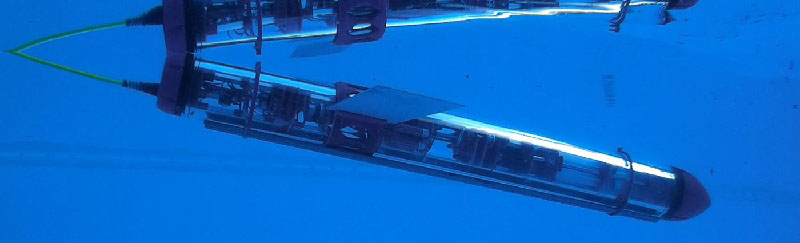
Grand Prize Winner ($50,000 USD): The Open Source Underwater Glider is an AUV (Autonomous Underwater Vehicle) capable of long-term underwater exploration of submarine environments. Where most AUVs are limited in both power and range, the Open Source Underwater Glider does not use active propulsion such as thrusters or propellers. This submersible glides, extending the range and capabilities of whatever task it is performing.

The Open Source Underwater Glider is built from off-the-shelf hardware, allowing anyone to build their own copy of this very capable underwater drone. Extended missions of up to a week are possible, after which the Glider would return home autonomously.

Connected Health: Open source IoT patient monitor

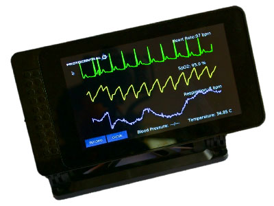
Second Place ($20,000): The Connected Health project aims to bring vital sign monitoring to the masses with a simple, inexpensive unit built around commodity hardware. This monitoring system is connected to the Internet, which enables remote patient monitoring.

Assistance System for Vein Detection

Third Place ($15,000): This Assistance System for Vein Detection uses off-the-shelf components and near-IR imaging to detect veins under the skin. This system uses a Raspberry Pi and camera module or a modified webcam and yet is just as reliable as professional solutions that cost dozens of times more than this team’s prototype.

Adaptive Guitar

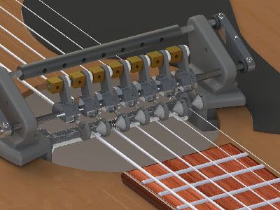
Fourth Place ($10,000): The Adaptive Guitar is an electromechanical system designed to allow disabled musicians to play the guitar with one hand (and a foot). This system strums the strings of a guitar while the musician frets each string.

Tipo : Braille Smartphone Keypad

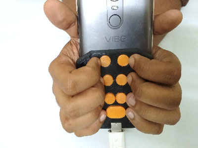
Fifth Place ($5,000): Tipo is effectively a Braille USB keyboard designed for smartphones. The advent of touchscreen-only phones has unfortunately left the visually impaired without a modern phone. Tipo allows for physical interaction with modern smartphones.

Best Product Winner: Tipo : Braille Smartphone Keypad

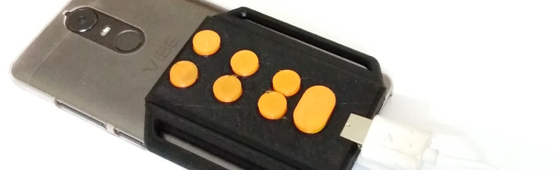
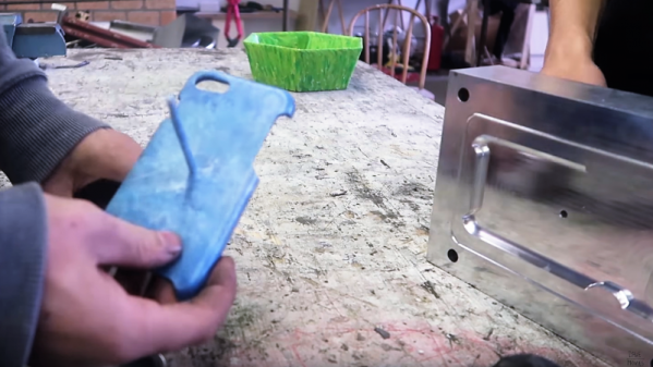
The winner of the Best Product is Tipo : Braille Smartphone Keypad. Tipo is the solution to the problem of the increasingly buttonless nature of modern smartphones. A phone that is only a touchscreen cannot be used by the visually impaired, and Tipo adds a Braille keypad to the back of any phone. It is effectively a USB keypad, designed for Braille input, that attaches to the back of any phone.

The Best Product competition ran concurrently with the five challenge rounds and asked entrants to go beyond prototype to envision the user’s needs, manufacturing, and all that goes into getting to market. By winning the Best Product competition, the creators of Tipo will refine their design, improve their mechanical build, start looking at injecton molding, and turn their 3D printed prototype into a real product that has the ability to change lives.

Congratulations to all who entered the Hackaday Prize. Taking time to apply your skill and experience to making the world better is a noble pursuit. It doesn’t end with the awarding of a prize. We have the ability to change lives by supporting one another, improving on great ideas, and sharing the calling to Build Something that Matters.

Snail Is Actually Cleverly Strange Geocaching Waypoint

Basic geocaching consists of following GPS coordinates to a location, then finding a container which is concealed somewhere nearby. Like any activity, people tend to add their own twists to keep things interesting. [Jangeox] recently posted a video of the OLED Snail 2.0 to show off his most recent work. (This is a refinement of an earlier version, which he describes in a blog post.)

Another of [Jangeox]’s Electronic Waypoints
[Jangeox] spices up geocaching by creating electronic waypoints, and the OLED Snail is one of these. Instead of GPS coordinates sending someone directly to a goal, a person instead finds a waypoint that reveals another set of coordinates and these waypoints are followed like a trail of breadcrumbs.

A typical waypoint is an ATTINY85 microcontroller programmed to display an animated message on the OLED, and the message reveals the coordinates to the next waypoint. The waypoint is always cleverly hidden, and in the case of the OLED Snail 2.0 the enclosure is the shell of a large snail containing the electronics encased in resin. This means that the devices have a finite lifespan — the battery sealed inside is all the power the device gets. Fortunately, with the help of a tilt switch the electronics can remain dormant until someone picks it up to start the show. Other waypoints have included a fake plant, and the fake bolt shown here. Video of the OLED Snail 2.0 is embedded below.

Continue reading “Snail Is Actually Cleverly Strange Geocaching Waypoint”

Fluid Simulations In The Kitchen Sink

In an age of ultra-powerful GPUs and cheap processors, computational techniques which were once only available to those with a government-sized R&D budgets are now available to the everyday hacker. An example of industry buzzword turned desktop software is the field of “computational fluid dynamics”, which put simply allow modeling how gasses or liquids will behave when moving through a cavity under specific conditions. Extensive utilization of these fluid simulations are often cited as one of breakthrough techniques which allowed SpaceX to develop their engine technology so rapidly when compared to Apollo and Shuttle era methods.

But just because anyone with a decent computer has access to the technology used for developing rocket engines doesn’t mean they have to use it. What if you prefer to do things the old-fashioned way? Or what if, let’s me honest, you just can’t figure out how to use software like Autodesk CFD and OpenFOAM? That’s exactly where [Desi Quintans] found himself when developing GUST, his cooling duct for i3-type 3D printers.

[Desi] tried to get the big name fluid simulation projects working with his prototype designs for an improved cooling duct, but had no end of trouble. Either the learning curve was too steep, or the simulation wasn’t accurate enough to give him any useful data. But remembering that air is itself a fluid, [Desi] took his simulation from the computer to the sink in order to better visualize what his cooling duct was doing to the airflow.

[Desi] printed up a box with a hole in the bottom that would connect up to his nozzles under test. As the volume of water in the box would be a constant between tests, he reasoned that this would allow him to evaluate the different nozzles at the same pressure. Sure enough, he found that the original nozzle design he was using caused chaotic water flow, which backed up what he was seeing in his experiments when mounted onto the printer.

After several iterations he was able to tame the flow of water by using internal baffles and fins, which when tested in water created something of a laminar flow effect. When he tried this version on the printer, he saw a clear improvement in part cooling, verifying that the behavior of the air and water was close enough for his purposes.

We’ve seen other projects that successfully used fluid simulations in their design before, but the quick and dirty test procedure [Desi] came up with certainly has its charms.

DIY Injection Mold Design For The Home Shop

3D printing is great for prototyping, and not bad for limited runs of parts. Unfortunately though it really doesn’t scale well beyond a few pieces, so when you’re ready for the mass market you will need to think about injection molding your parts. But something like that has to be farmed out, right? Maybe not, if you know a thing or two about designing your own injection molds.

The video below comes from [Dave Hakkens] by way of his Precious Plastic project, whose mission it is to put the means of plastic recycling into the hands of individuals, rather than relying on municipal programs.  We’ve covered their work before, and it looks like they’ve come quite a way to realizing that dream. This tutorial by [Dave]’s colleague [Jerry] covers the basic elements of injection mold design, starting with 3D modeling in Solidworks. [Jerry] points out the limitations of a DIY injection molding effort, including how the thickness of parts relates to injection pressure. Also important are features like gentle curves to reduce machining effort, leaving proper draft angles on sprues, and designing the part to ease release from the mold. [Jerry] and [Dave] farmed out the machining of this mold, but there’s no reason a fairly complex mold couldn’t be produced by the home gamer.

When you’re done learning about mold design, you’ll be itching to build your own injection mold machine. Precious Plastic’s tutorial looks dead simple, but this machine looks a little more capable. And why CNC your molds when you can just 3D print them?

Continue reading “DIY Injection Mold Design For The Home Shop”