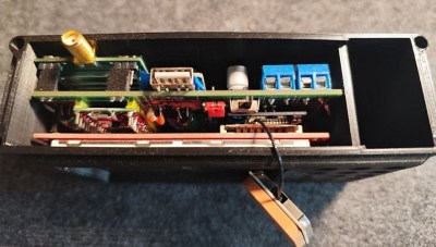
The Mouse Language, Running On Arduino

Although plenty of us have our preferred language for coding, whether it’s C for its hardware access, Python for its usability, or Fortran for its mathematic prowess, not every language is specifically built for problem solving of a particular nature. Some are built as thought experiments or challenges, like Whitespace or Chicken but aren’t used for serious programming. There are a few languages that fit in the gray area between these regions, and one example of this is MOUSE, which can now be run on an Arduino.

Although MOUSE was originally meant to be a minimalist language for computers of the late 70s and early 80s with limited memory (even for the era), its syntax looks more like a more modern esoteric language, and indeed it arguably would take a Python developer a bit of time to get used to it in a similar way. It’s stack-based, for a start, and also uses Reverse Polish Notation for performing operations. The major difference though is that programs process single letters at a time, with each letter corresponding to a specific instruction. There have been some changes in the computing world since the 80s, though, so [Ivan]’s version of MOUSE includes a few changes that make it slightly different than the original language, but in the end he fits an interpreter, a line editor, graphics primitives, and peripheral drivers into just 2 KB of SRAM and 32 KB Flash so it can run on an ATmega328P.

There are some other features here as well, including support for PS/2 devices, video output, and the ability to save programs to the internal EEPROM. It’s an impressive setup for a language that doesn’t get much attention at all, but certainly one that threads the needle between usefulness and interesting in its own right. Of course if a language where “Hello world” is human-readable is not esoteric enough, there are others that may offer more of a challenge.


Image Credit: Maxbrothers2020

Plugging Plasma Leaks In Magnetic Confinement With New Guiding Center Model

Although the idea of containing a plasma within a magnetic field seems straightforward at first, plasmas are highly dynamic systems that will happily escape magnetic confinement if given half a chance. This poses a major problem in nuclear fusion reactors and similar, where escaping particles like alpha (helium) particles from the magnetic containment will erode the reactor wall, among other issues. For stellarators in particular the plasma dynamics are calculated as precisely as possible so that the magnetic field works with rather than against the plasma motion, with so far pretty good results.

Now researchers at the University of Texas reckon that they can improve on these plasma system calculations with a new, more precise and efficient method. Their suggested non-perturbative guiding center model is published in (paywalled) Physical Review Letters, with a preprint available on Arxiv.

The current perturbative guiding center model admittedly works well enough that even the article authors admit to e.g. Wendelstein 7-X being within a few % of being perfectly optimized. While we wouldn’t dare to take a poke at what exactly this ‘data-driven symmetry theory’ approach exactly does differently, it suggests the use machine-learning based on simulation data, which then presumably does a better job at describing the movement of alpha particles through the magnetic field than traditional simulations.

Top image: Interior of the Wendelstein 7-X stellarator during maintenance.

Various hardware components laid out on a workbench.

Working On Open-Source High-Speed Ethernet Switch

Our hacker [Andrew Zonenberg] reports in on his open-source high-speed Ethernet switch. He hasn’t finished yet, but progress has been made.

If you were wondering what might be involved in a high-speed Ethernet switch implementation look no further. He’s been working on this project, on and off, since 2012. His design now includes a dizzying array of parts. [Andrew] managed to snag some XCKU5P FPGAs for cheap, paying two cents in the dollar, and having access to this fairly high-powered hardware affected the project’s direction.

Continue reading “Working On Open-Source High-Speed Ethernet Switch”

Stylus Synth Should Have Used A 555– And Did!

For all that “should have used a 555” is a bit of a meme around here, there’s some truth to it. The humble 555 is a wonderful tool in the right hands. That’s why it’s wonderful to see this all-analog stylus synth project by EE student [DarcyJ] bringing the 555 out for the new generation.

The project is heavily inspired by the vintage stylophone, but has some neat tweaks. A capacitor bank means multiple octaves are available, and using a ladder of trim pots instead of fixed resistors makes every note tunable. [Darcy] of course included the vibrato function of the original, but no, he did not use a 555 for that, too. He used an RC oscillator. He put a trim pot on that, too, to control the depth of vibrato, which we don’t recall seeing on the original stylophone.

The writeup is very high quality and could be recommended to anyone just getting started in analog (or analogue) electronics– not only does [Darcy] explain his design process, he also shows his pratfalls and mistakes, like in the various revisions he went through before discovering the push-pull amplifier that ultimately powers the speaker.

Since each circuit is separately laid out and indicated on the PCB [Darcy] designed in KiCad for this project. Between that and everything being thru-hole, it seems like [Darcy] has the makings of a lovely training kit. If you’re interested in rolling your own, the files are on GitHub under a CERN-OHL-S v2 license,  and don’t forget to check out the demo video embedded below to hear it in action.

Of course, making music on the 555 is hardly a new hack. We’ve seen everything from accordions to paper-tape player pianos to squonkboxes over the years. Got another use for the 555? Let us know about it, in the inevitable shill for our tip line you all knew was coming.


As The World Burns, At Least You’ll Have Secure Messaging

There’s a section of our community who concern themselves with the technological aspects of preparing for an uncertain future, and for them a significant proportion of effort goes in to communication. This has always included amateur radio, but in more recent years it has been extended to LoRa. To that end, [Bertrand Selva] has created a LoRa communicator, one which uses a Pi Pico, and delivers secure messaging.

The hardware is a rather-nice looking 3D printed case with a color screen and a USB A port for a keyboard, but perhaps the way it works is more interesting. It takes a one-time pad approach to encryption, using a key the same length as the message. This means that an intercepted message is in effect undecryptable without the key, but we are curious about the keys themselves.

They’re a generated list of keys stored on an SD card with a copy present in each terminal on a particular net of devices, and each key is time-specific to a GPS derived time. Old keys are destroyed, but we’re interested in how the keys are generated as well as how such a system could be made to survive the loss of one of those SD cards. We’re guessing that just as when a Cold War spy had his one-time pad captured, that would mean game over for the security.

So if Meshtastic isn’t quite the thing for you then it’s possible that this could be an alternative. As an aside we’re interested to note that it’s using a 433 MHz LoRa module, revealing the different frequency preferences that exist between enthusiasts in different countries.

Continue reading “As The World Burns, At Least You’ll Have Secure Messaging”

The Make-roscope

Normal people binge-scroll social media. Hackaday writers tend to pore through online tech news and shopping sites incessantly. The problem with the shopping sites is that you wind up buying things, and then you have even more projects you don’t have time to do. That’s how I found the MAKE-roscope, an accessory aimed at kids that turns a cell phone into a microscope. While it was clearly trying to appeal to kids, I’ve had some kids’ microscopes that were actually useful, and for $20, I decided to see what it was about. If nothing else, the name made it appealing.

My goal was to see if it would be worth having for the kinds of things we do. Turns out, I should have read more closely. It isn’t really going to help you with your next PCB or to read that tiny print on an SMD part. But it is interesting, and — depending on your interests — you might enjoy having one. The material claims the scope can magnify from 125x to 400x.

What Is It?

A microscope in a tin. Just add a cell phone or tablet

The whole thing is in an unassuming Altoids-like tin. Inside the box are mostly accessories you may or may not need, like a lens cloth, a keychain, plastic pipettes, and the like. There are only three really interesting things: A strip of silicone with a glass ball in it, and a slide container with five glass slides, three of which have something already on them. There’s also a spare glass ball (the lens).

What I didn’t find in my box were cover slips, any way to prepare specimens, and — perhaps most importantly — clear instructions. There are some tiny instructions on the back of the tin and on the lens cloth paper. There is also a QR code, but to really get going, I had to watch a video (embedded below).

Continue reading “The Make-roscope”

We can see the internal pads from an integrated circuit where the epoxy has been ground away.

When Repairs Go Inside Integrated Circuits

What can you do if your circuit repair diagnosis indicates an open circuit within an integrated circuit (IC)? Your IC got too hot and internal wiring has come loose. You could replace the IC, sure. But what if the IC contains encryption secrets? Then you would be forced to grind back the epoxy and fix those open circuits yourself. That is, if you’re skilled enough!

In this video our hacker [YCS] fixes a Mercedes-Benz encryption chip from an electronic car key. First, the black epoxy surface is polished off, all the way back to the PCB with a very fine gradient. As the gold threads begin to be visible we need to slow down and be very careful.

The repair job is to reconnect the PCB points with the silicon body inside the chip. The PCB joints aren’t as delicate and precious as the silicon body points, those are the riskiest part. If you make a mistake with those then repair will be impossible. Then you tin the pads using solder for the PCB points and pure tin and hot air for the silicon body points.

Once that’s done you can use fine silver wire to join the points. If testing indicates success then you can complete the job with glue to hold the new wiring in place. Everything is easy when you know how!

Does repair work get more dangerous and fiddly than this? Well, sometimes.

Continue reading “When Repairs Go Inside Integrated Circuits”