[Bill Meara] has finished up his radio. It both looks and sounds great. It was only a few weeks ago that [Bill] posted a guest rant here on Hackaday. The Radio he mentioned building in the rant is now complete. The transceiver itself is a BITX, a 14MHz Single Sideband (SSB) radio designed by Ashhar Farhan VU2ESE. Ashhar designed the BITX as a cheap to build, and easy to tune up transceiver for radio amateurs in India.
By utilizing parts easily sourced from scrapped TV sets, the BITX can be built for less than 300 Indian Rupee – or about $4.70 USD. In [Bill]’s own words, “Five bucks and some sweat equity gets you a device capable of worldwide communication.” He’s not kidding either. [Bill’s] first QSO was with a ham in the Azores Islands of Portugal.
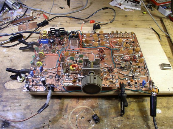
[Bill] built his radio using the “Manhattan” building style, which we’ve seen before. Manhattan style uses rectangular pads glued down onto a copper ground plane. It makes for a more flexible design than regular old dead bug style building. Looking at all those components may be a bit daunting at first, but plenty of support is available. [Bill] has an 18 part build log on the soldersmoke website. There also is an active yahoo group dedicated to the BITX.
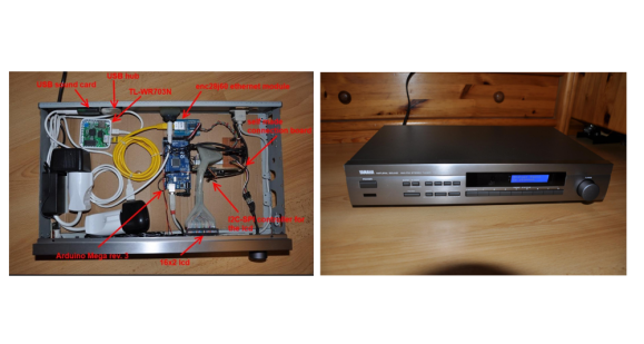 [Raffael] had an old Broken Yamaha natural sound receiver lying around. Rather than throw it out,


