Raspberry Pi boards are no longer constrained – these days, you can get a quad-core board with 8 or 16GB of RAM to go around, equip it with a heatsink, and get a decently comfortable shop/desk/kitchen computer with GPIOs, cameras, speedy networking, maybe even NVMe, and all the wireless you’d expect.
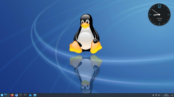
Raspberry OS, however, remains lightweight with its pre-installed LXDE environment – and, in many cases, it feels quite constrained. In case you ever idly wondered about giving your speedy Pi a better UI, [Luc] wants to remind you that setting up KDE on your Raspberry OS install is dead simple and requires only about a dozen commandline steps.
[Luc] walks you through these dozen steps, from installation to switching the default DE, and the few hangups you might expect after the switch; if you want to free up some disk space afterwards, [Luc] shows how to get rid of the original LXDE packages. Got the latest Trixie-based Pi OS? There’s an update post detailing the few necessary changes, as well as talking about others’ experiences with the switch.
All in all, [Luc] demonstrates that KDE will have a fair bit of graphical and UX advantages, while operating only a little slower, and if you weren’t really using your powerful Pi to the fullest, it’s a worthwhile visual and usability upgrade. For the regular desktop users, KDE has recently released their own distro, and our own [Jenny] has taken a look at it.