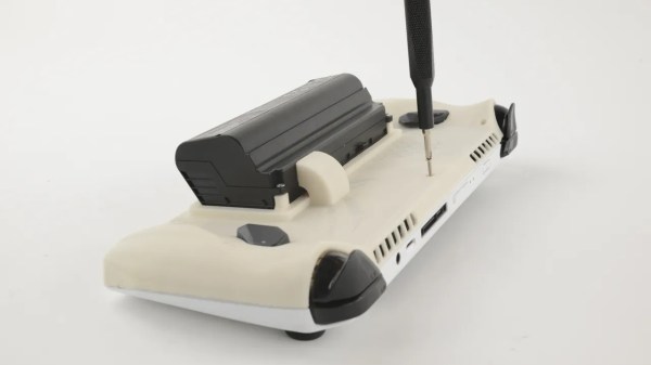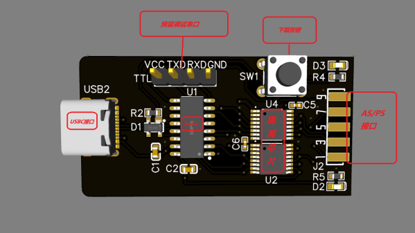
Here’s a CH552G-based USB Blaster project from [nickchen] in case you needed more CH552G in your life, which you absolutely do. It gives you the expected IDC-10 header ready for JTAG, AS, and PS modes. What’s cool, it fits into the plastic shell of a typical USB Blaster, too!
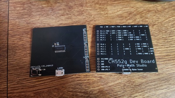
The PCB is flexible enough, and has all the features you’d expect – a fully-featured side-mounted IDC-10 header, two LEDs, a button for CH552 programming mode, and even a UART header inside the case. There’s an option to add level shifter buffers, too – but you don’t have to populate them if you don’t want to do that for whatever reason! The Hackaday.io page outlines all the features you are getting, though you might have to ask your browser to translate from Chinese.
Sadly, there’s no firmware or PCB sources – just schematics, .hex, BOM, and Gerber .zip, so you can’t fix firmware bugs, or add the missing USB-C pulldowns. Nevertheless, it’s a cool project and having the PCB for it is lovely, because you never know when you might want to poke at a FPGA on a short notice. Which is to say, it’s yet another CH552 PCB you ought to put in your PCB fab’s shopping cart! This is not the only CH552G-based programming dongle that we’ve covered – here’s a recent Arduino programmer that does debugWire, and here’s like a dozen more different CH552G boards, programmers and otherwise.