Use Your Mouse Pointer To Send Data

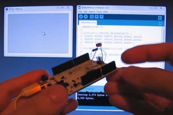
[Ido Gendel] was thinking about new and interesting ways to send data between devices, when he realized that the answer was right in his hand. Literally: he decided to try sending data using the mouse pointer. What he came up with was an interesting hack that uses small movements of the mouse pointer to send data at up to 1200bps, or about 150 bytes per second.

The way he did this was very, very clever. He used an Arduino Leonardo that is set to emulate a mouse, working alongside his existing mouse. This setup means that he can use his existing mouse: the system just sees the Arduino as a second mouse, and the pointer just looks a little jerky when you zoom in. That is because the Arduino is just sending tiny movements, each of which is a code that represents a nybble (4 binary bits) of data. By using both a combination of three left-right or up-down movements, he was able to create 16 movements, each of which can encode 4 bits of data. Each of these encoding movements also returns the mouse to its origin point, so the mouse doesn’t mysteriously scroll off the screen when data is being sent.

Continue reading “Use Your Mouse Pointer To Send Data”

Driving A 7 Segment LED Display From An FT232

Sometimes, a good hack is about using less rather than more. That’s the case with this neat tutorial from [Rahul.S] on driving a 7-segment LED display with an FT232. By using this cheap USB to serial controller, [Rahul.S] was able to drive the display directly without using a microcontroller, which keeps the component cost down.

He’s bit banging an octal buffer connected to the display. You may be surprised to find that the FT232 chips do have enough outputs to make this work. Rather than send serial data number to the display and have a controller convert this into a set of signals that make the number, this conversion is done by the PC, which then sends a signal that directly illuminates the appropriate parts of the LED. By using all of the available output lines of the FT232 (including ones like the RTS/CTS line that are usually used for signalling), [Rahul.S] was able to drive all seven of the elements and the decimal point.

Of course, cynics may argue that it would be simpler to use a cheap serial LCD display. That is true, but there is always something to be said for knowing how to do something yourself rather than letting others do it for you… Continue reading “Driving A 7 Segment LED Display From An FT232”

Witness The Birth Of A 36-Lens Panoramic Camera

We are suckers for a teardown video here at Hackaday: few things are more fascinating than watching an expensive piece of equipment get torn apart. [Jonas Pfeil] is going the other way, though: he has just published an interesting video of one of his Panono panoramic ball cameras being built.

The Panono is a rather cool take on the panoramic camera: it is a ball-shaped device fitted with 36 individual cameras. When you press the button and throw the camera in the air, it waits until the highest point and then takes pictures from all of the cameras. Sound familiar? We first coverd [Jonas’] work way back in 2011.

Photos are stitched together into a single panoramic image with an equivalent resolution of up to 106 megapixels. The final image is panoramic in both horizontal and vertical directions: you can scroll up, down, left, right or in and out of the image. Since images are all taken at the same time you don’t have continuity problems associated with moving a single camera sensor. There are a number of sample images on their site but keep reading for a look at some of the updated hardware since our last look at this fascinating camera.

Continue reading “Witness The Birth Of A 36-Lens Panoramic Camera”

Hipster Rotary Dial Adds Bluetooth 4.0

We have seen a few projects that convert a rotary dial for use with modern technology, but this one adds a new twist to the mix: it uses Bluetooth 4.0. [Silent] used a Nordic Semiconductor NRF51 DK development board for the project, which was built from the Nordic SDK source code for creating an HID (Human Interface Device). After what he claims was an hour or so of hacking, he was able to get this Arduino-compatible SoC dev board to detect the pulses from the rotary dial, then pass the appropriate number to a connected device as a key press. This means that his design should work with any device that has Bluetooth 4.0 support. It is powered from a big dry cell because, to quote [Silent], “small coin batteries are not hipster enough”.

It’s a simple project, and we have seen rotary cell phones before, but this still is ripe for expansion. You could either use a smaller, cheaper version of the Nordic chip at the center of this hack, as most of the dev board features aren’t used. Or you could do some more hacking, add support for the Bluetooth HSP headset profile, then wire it up to a vintage phone for the most hipster Bluetooth headset ever. We can’t wait until we see a hipster sitting in a coffee shop banging away on a typewriter and answering this. Get to it, people!

Continue reading “Hipster Rotary Dial Adds Bluetooth 4.0”

Sphero Riding Strandbeest Is A Robot With An Exoskeleton

[Theo Jansen] makes awesome things called Strandbeests; wind-driven automatons that roam beaches and art galleries. It has long been one of our favorite mechanisms. Newer, but also a favorite is the Sphero smartphone controlled orb. The combination of the two is epic!

You may remember seeing Sphero used to create a tiny BB8 replica. Inside the orb is a tiny robot capable of rolling itself hamster-wheel-style in any direction. It’s a rather powerful bot and that makes Sphero fast. The high RPM is what makes this hack possible. Sphero spins rapidly while perched on some rollerblade wheels. Gearing converts this to the rolling motion of the Strandbeest.

The original concept was posted a year ago but it was just now brought to our attention by [fhareide]  who is working on his own smaller Strandbeest driven by a Sphero. Since there are no assembly details on the original posting, you can follow along with [fhareide’s] documentation in order to complete your own build. So far [fhareide] imported the STL model into Autodesk Inventor, printed out one set of gears to insure the printer resolution could handle it, and assembled one set of legs.
We think of this as a kind of exoskeleton for a Sphero. We’ll keep an eye on this through the assembly, testing the drive mechanism and then the point where the whole thing becomes self-aware and either runs away to hide or terminates him.

Continue reading “Sphero Riding Strandbeest Is A Robot With An Exoskeleton”

You Own Your MRI Brainscan; Do Something Interesting With It

The most complicated and fascinating gadget you will ever own is your brain. Why not pay tribute to this wonder by creating a 3D scale model that you can print yourself? If you have had a full-head MRI scan, it is simple to take this data and create a 3D model that you can print out on any 3D printer. Here’s how to print your brain.

To begin, you are going to need an MRI scan. Unfortunately, the low-field MRI that [Peter Jansen] is working on won’t quite cut it (yet): you’ll have to get the pros to do it. The type of scan also matters, because we want a scan that focusses in on the brain itself, not the bits around it. What type you get depends on what your doctor wants to know, as the radiologist can run a lot of different scans and analysis of the data to show different types of tissue. After looking through the scans that I got, I settled on one that was labelled eB1000i(BRAIN) With and Without Contrast. To a radiologist, that information means a lot, telling you what type of scan it is, and that it was done with a contrast agent, a metal dye that is injected to make water-rich tissues (like my brain) more visible. The number refers to something called the diffusion weighting, which helps the doctor look for swelling that can indicate things like strokes, tumors, etc. There’s a good guide to some of the jargon here.

Continue reading “You Own Your MRI Brainscan; Do Something Interesting With It”

Build A Sensor Network Around A Weather Station

[Yveaux] had a problem. The transmitter on his outdoor weather station had broken, rendering the inside display useless. He didn’t want to buy a new one, so, like the freelance embedded software designer that he is, he decided to reverse engineer the protocol that the transmitter uses and build his own. He didn’t just replace the transmitter module, though, he decided to create an entire system that integrated the weather system into a sensor network controlled by a Raspberry Pi. That’s a far more substantial project, but it gave him the ability to customize the display and add more features, such as synching the timer in the display with a network clock and storing the data in an online database.

Fortunately for [Yveaux], the transmitter itself was fairly easy to replace. The weather station he had, like most, transmitted on the 868MHz frequency, which is a license-free ISM (Industrial, Scientific and Monitoring) spot on the spectrum. After some poking around, he was able to figure out the protocol and teach the Pi to speak it. He then added a Moteino and an nRF2401+ transmitter to the weather station, so it can send data to the Pi, which then sends it to the display. It is a more complicated setup, but it is also much more flexible. He’s had it running for a couple of years now and has collected more than a million sensor readings.