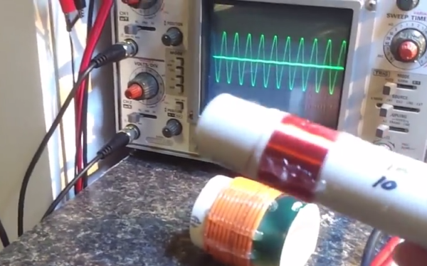
[James] has a friend who teaches at the local community college. When this friend asked him to build a transformer coupling simulation, he was more than happy to oblige. Fortunately for us, he also made a video that explains what is happening while showing the output on a ‘scope.
For the simulation, [James] built primary and secondary coils using PVC pipe. The primary coil consists of 11 turns of 14AWG stranded wire with 4V running through it applied. The first secondary he demonstrates is similarly built, but has 13 turns. As you’ll see, the first coil induces ~1.5V in the second coil. [James] first couples it with the two windings going the same way, which results in the two 2Mhz waveforms being in phase with each other. When he inserts the secondary the other way, its waveform is out of phase with the primary’s.
His second secondary has the same diameter PVC core, but was wound with ~60 turns of much thinner wire—28AWG bell wire to be exact. This match-up induces 10V on the secondary coil from the 4V he put on the primary. [James]’ demonstration includes a brief Lissajous pattern near the end. If you don’t know enough about those, here’s a good demonstration of the basics coupled with an explanation of the mechanics behind them.
Continue reading “Transformer Inductive Coupling Simulation Is SFW”

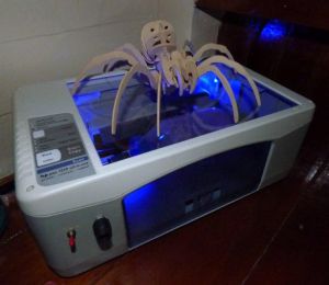 Don’t throw out that old printer! Not that you would, but even if you’ve already scavenged it for parts, you can
 This project is
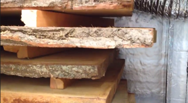
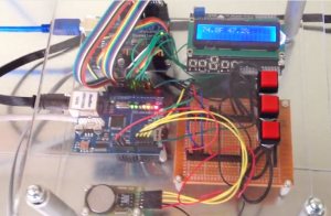 The kiln is built from slightly blemished pallet rack shelving that [Tim] cut to suit his needs. He skinned it with 1/2″ insulation boards sealed with aluminium tape and plans to add sheet metal to protect the insulation.