SBITX: Hackable HF SDR For The Raspberry Pi

Cheap, easy to use SDR dongles are an immensely powerful tool for learning about radio technology. However, building your own SDR is not something too many hackers are confident to tackle. [Ashhar Farhan, VU2ESE] hopes to change this with the sBITX, a hackable HF SDR transceiver designed around the Raspberry Pi.

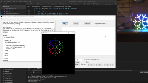
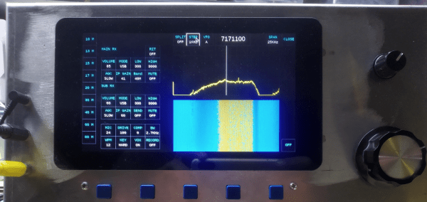
[Ashhar] introduced the project in talk at the virtual “Four Days In May” annual conference of the QRP Amateur Radio Club International. Watch the full talk in the video after the break. He first goes over the available open source SDR radios, and then delves into his design decisions for the sBITX. One of the primary goals of the project was to lower the barrier of entry. To do this, he chose the Raspberry Pi as base, and wrote C code that that anyone who has done a bit of Arduino programming should be able to understand and modify. The hardware is designed to be as simple as possible. On the receive side, a simple superheterodyne architecture is used to feed a 25 kHz wide slice of RF spectrum to an audio codec, which send the digitized audio to the Raspberry Pi. The signal is then demodulated in software using FFT. For transmit, the signal is generated in software, and then upconverted to the desired RF frequency. [Ashhar] also created a GUI for the 7″ Raspberry Pi screen.

At the moment the sBITX is still in the development stage, information is spread between the video after the break, it’s accompanying PDF, the GitHub repo, and a thread on the BITX20 group.

[Ashar Farhan] is well known in the ham radio community for low cost radio designs like the BITX, and it’s successor, the μBITX. He also created the Antuino, an Arduino based antenna tester. Continue reading “SBITX: Hackable HF SDR For The Raspberry Pi”

Magnus-Effect RC Aircraft Is A Lot Harder Than It Looks

Conventional airfoil wings have come out on top for getting flying machines airborne over the last century, but there were a few other interesting designs that have come and gone. One of these is the Magnus effect plane, which makes use of the lift produced by a spinning cylinder. [James Whomsley] from [Project Air] decided to build one as a side project, but it ended up being a lot more challenging than what he initially suspected. (Video, embedded below.)

The Magnus effect achieved a bit of viral fame a few years when [How Ridiculous] dropped a basketball down a dam wall with some backspin. [James] T-shaped Magnus effect plane has a pair of spinning cylinders at the top to create lift, driven by a brushless motor using a belt. A second brushless motor with a propeller is on the center carbon fiber tube provides forward thrust, and a rudder provides yaw control. The battery is attached to the bottom of the tub for stability.

The very first flight looked very promising, but [James] quickly ran into a series of problems related to center of gravity, power, pitch control, and drag. After iterations of the build-crash-rebuild cycle, he ended up with larger motors and rudder, shorter “wings”, and a higher thrust motor position. This resulted in a craft still only marginally controllable, but stayed in the air for quite a while. Since the intention was never to turn it into a long-term project, James] called it a success to avoid more yak shaving, and continue work on his airboat and rocketplane.

If you are interested in building one of your own, he put all the findings of his experimentation in a short report. For more inspiration, check out the other Magnus effect plane we covered that used KFC buckets for the wings.

Continue reading “Magnus-Effect RC Aircraft Is A Lot Harder Than It Looks”

Upgrade A 3D Printed CNC Milling Machine By Using It

One of the original ideas behind the RepRap project was for the machines to create their own upgrades. That philosophy is shining brightly in [Ivan Miranda] CNC milling machine project, which has been used to upgrade its aluminum and 3D printed frame components to steel.

For precision machining on hard metal, machine rigidity is of utmost importance. [Ivan]’s original CNC mill made extensive use of lightweight aluminum extrusions with 3D printed fittings. The machine worked, but the lack of rigidity was visible in the surface quality of the machine parts. The latest upgrade included a completely new frame from welded steel tubing and heavy aluminum mounting plates. The original machine was used to slowly machine slots in the steel tubes to retain the adjustability of the Z-axis. Some of the 3D printed motor mounts remained, so in the second video after the break [Ivan] used the newly upgraded machine to mill some aluminum replacements.

While this machine might not be perfect, we have to respect [Ivan]’s willingness to toss himself in at the deep end and show all failures and lessons learned the hard way. This project was clearly used as an opportunity to improve his welding and machining skills. His fabrication skills have come a long way from mainly 3D printed projects like the giant tracked tank and screw tank.

Continue reading “Upgrade A 3D Printed CNC Milling Machine By Using It”

Cablecam Is An Exercise In System Integration

Drones have become the standard for moving aerial camera platforms, but another option that sees use in the professional world are cable cameras. As an exercise in integrating mechanics, electronics, and software, [maxipalay] created his own Cablecam.

Cablecam is build around a pair of machined wood plates, with some pulleys and motor reduction gearing between them. A brushless hobby motor moves the platform along the rope/cable, driven a drone ESC. Since the ESC doesn’t have a reverse function, [maxipalay] used four relays controlled by an Arduino to swap around the connections of two of the motor wires to reverse direction. The main onboard controller is a Raspberry Pi, connected to a camera module mounted on a two-axis gimbal for stabilization. A GPS module was also added for positioning information on long cables.

The base station is built around an Nvidia Jetson Nano connected to a 7″ screen mounted in a plastic case. Video, telemetry and control signals are communicated using the open-source Wifibroadcast protocol. This uses off-the-shelf WiFi hardware in connectionless mode to broadcast UDP packets, and avoids the lengthy WiFi reconnection process every time a connection drops out. The motion of Cablecam can be controlled manually using a potentiometer on the control station, or use the machine vision capabilities of the Jetson to automatically track and follow people.

We’ve seen several cable robots over the years, including a solar-powered sensor platform that resembles a sloth.

3D Printer Automated Bed Swapping System Loads From A Magazine

FDM 3D printing has gone beyond prototyping and is being used as a production tool by many companies. However, conventional printers still require an operation to pop the finished part of the bed and start a new print. [Thomas Sandladerer] wanted a way to swap beds without human intervention, so he built an automatic print surface changing system.

The most obvious solution to this problem may appear to be belt printers like the Creality CR-30, but these come with some trade-offs. Bed adhesion can be a problem, and the lack of a rigid print surface causes some parts to come out warped. [Thomas] wanted to be able to use PEI-coated steel beds to avoid these issues. His solution is a system that pulls beds from a “magazine” and pushed out the old bed after a part is finished. It still uses a magnetic heatbed, which lowers out of the way before changing print surfaces. Each print surface is fitted inside a 3D printed frame which rests on the tool changer frame and keeps it in place as the heatbed drops down. The bed frames are printed using ASA, can handle 90 C without problems. The pusher mechanism and the heatbed lowering system are driven by stepper motors which connect to the spare motor outputs on the printer’s control board. The printer in question is a Voron 2.4, which is perfect for this application thanks to its high print speed.

This tool-changing system is only the first prototype, but it still worked very well. [Thomas] plans to make key improvements like a larger print bed and reduced height. This system might be a good fit for small and large print farms. We’ve seen another bed-clearing system that doesn’t require extra build surfaces, but instead scrapes off the completed part.

Continue reading “3D Printer Automated Bed Swapping System Loads From A Magazine”

Strangest Upside-Down 3D Printer Fits In A Filament Box

It’s rare these days for a new FDM printer to come along that sparks our interest, but the [Kralyn]’s Positron managed to do it. (Video, embedded below.) It prints upside down and packs down into a filament box while still boasting a print volume of 175 mm x 176 mm x 125 mm.

Unlike most 3D printers, the hotend and XY-gantry is mounted below the build plate, directly onto the base. You might assume that a printer needs to extrude plastic with gravity to work properly, but the real action is in the smooshing of the plastic layers. It appears that it might even improve bridging since the hotend is supporting the plastic as it gets extruded. A clear glass build plate is used, with the same heating strips found on the rear windows of most cars. This also allows the user still see the part, and provides the added advantage of being able to quickly spot bed leveling and adhesion problems.

Another interesting side effect of this arrangement is rigidity. There is no need to suspend the XY gantry with the heavy hotend in the air, so it can be mounted directly on the thick aluminum base plate. It uses an H-bot style gantry, with Synchromesh timing cables instead of belts, which eliminates the concern of belt twist. To get the best possible print volume within the size of a filament box, the gantry axes are arranged diagonally across the base plate. The Z-axis can disconnect and lay flat on top of the printer and uses the linear rails to keep it perfectly straight and perpendicular when mounted. Continue reading “Strangest Upside-Down 3D Printer Fits In A Filament Box”

Dedicated LED Animation Framework For ESP32

[Eric Arcana] has been creating animated holiday decorations for several years, which involved a lot of custom code to make things light up the way he wanted, pulling the microcontroller to make changes. Using ESP32s with remote software updates is easier, but [Eric] also wanted to make the code simpler. To achieve this he created Fade, a custom programming language/framework for controlling LED animations from the ESP32.

Fade is written for addressable RGB LEDs like the Neopixel/WS2812. It keeps track of the current color of every LED in the system and allows the user to define what color it should be at a specified time in the future. Time is specified using 10 ms clock cycles. The LEDs will smoothly change from one color to the other in the specified number of clock cycles, without needing to specify what the intermediate colors should be.

Code is written in simple IDE, running on a web server on the ESP32 itself, or on a remote Windows PC. The language is very simple, but still powerful enough to create complex LED animations. A key part of it is the ability to specify multiple concurrent state changes in just a few lines of code. [Eric] also included optioning to take touch button inputs and use them to update the animations. Another nice feature is a simulation window on the desktop IDE. It allows you to create custom LED layouts on PC, and test your code without needing to send it to the ESP32.

Addressable LEDs have made creating large LED installations a lot simpler, like this 6 foot LED ball or a LED Video Wall.

Continue reading “Dedicated LED Animation Framework For ESP32”