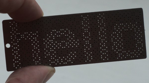
Visual cryptography is one of those unusual cases that kind of looks like a good idea, but it turns out is fraught with problems. The idea is straightforward enough — an image to encrypt is sampled and a series of sub-pixel patterns are produced which are distributed to multiple separate images. When individual images are printed to transparent film, and all films in the set are brought into alignment, an image appears out of the randomness. Without at least a minimum number of such images, the original image cannot be resolved. Well, sort of. [anfractuosity] wanted to play with the concept of visual cryptography in a slightly different medium, that of a set of metal plates, shaped as a set of keyrings.
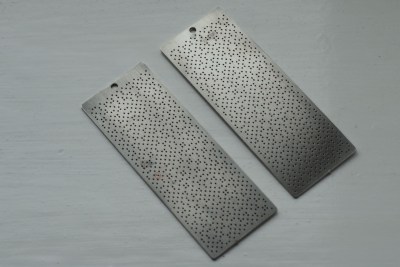
Metal blanks were laser cut, with the image being formed by transmitted light through coincident holes in both plate pairs, when correctly aligned. What, we hear you ask, is the problem with this cryptography technique? Well, one issue is that of faking messages. It is possible for a malicious third party, given either one of the keys in a pair, to construct a matching key composing an entirely different message, and then substitute this for the second key, duping both original parties. Obviously this would need both parties to be physically compromised, but neither would necessarily notice the substitution, if neither party knew the originally encrypted message. For those interested in digging in a little deeper, do checkout this classic paper by Naor and Shamir [pdf] of the Wiezmann Institute. Still, despite the issues, for a visual hack it’s still a pretty fun technique!
Want to learn a little more about crypto techniques you can do at home? Here’s our guide. Encryption too hard to break, but need a way to eavesdrop? Just punt out a flawed system, and you’re good to go.
Continue reading “Visual Cryptography For Physical Keyrings”