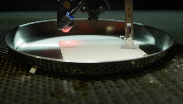
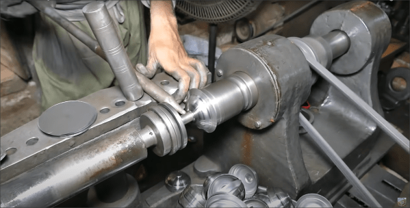
It appears they can. [Ian Charnas] wanted his very own Thor Hammer. He wasn’t happy to settle on the usual cosplay methods of spray painting over foam and similar flimsy materials. He presents a method for nickel plating onto a 3D printed model, using conductive nickel paint to prepare the plastic surface for plating. In order to reduce the use of hazardous chemistry, he simplifies things to use materials more likely to be found in the kitchen.
As the video after the break shows, [Ian] went through quite a lot of experimentation in order to get to a process that would be acceptable to him. As he says, “after all, if something is worth doing, it’s worth over-doing” which is definitely a good ethos to follow. Its fairly hard to plate metals and get a good finish, and 3D printed objects are by their nature, not terribly smooth. But, the effort was well rewarded, and the results look pretty good to us.
But what about the 400 kV I hear you ask? Well, it wouldn’t be Thor’s hammer, without an ungodly amount of lightning flying around, and since [Ian] is part of a tesla coil orchestra group, which well, it just kinda fell into place. After donning protective chainmail to cover his skin, he walks straight into the firing line of a large pair of musical tesla coils and survives for another day. Kind of makes his earlier escapade with jet-powered roller skates look mundane by comparison.
[Petteri Aimonen] presents for us a modular differential probe, as his entry into the 2021 Hackaday Prize.
This project shows a simple and well polished implementation of a differential-to-single-ended preamplifier, which allows a differential signal to be probed and fed to an oscilloscope via a BNC cable.
It implements a classic instrumentation amplifier, where we have two amplifier stages. The first gives us the options for a gain of either 1 or 10, if we need it, with the second stage having a gain of 2.
The remaining circuit is a power supply to generate the necessary dual-rail supplies to feed the opamps. There is a lot of filtering on those output rails as well as on the USB power input side to try keep all that switched-mode power supply noise out of the signal path.
There are a couple of interesting design choices including the use of PCB material for the long removable probe arms, that integrate PCB spark gaps to offer a first defence against ESD reaching the more delicate parts of the system.
Why This Is Useful
There are two main classes of signals we electronics engineers care about: single-ended and differential-mode.
With the first kind, the signal is carried on a single wire, which is defined as being referenced to the common system ground. Current flows along the wire and returns to its source along the path of least resistance, at least at low frequencies. At higher frequencies, the path of least inductance is more relevant. This is all well and good, so long as you design the PCB correctly.
Coupling from adjacent wires due to mutual capacitance and inductance, as well as noise in the reference ground all conspire to mangle the signal we want to pass down the wire.
As the frequencies increase, and especially if you’re dealing with sharp edges, with all that extra odd-harmonic power, things start to get bad real fast. The way we deal with this is by utilising differential-mode signalling. This is where instead of a single wire, referenced to some notion of ground, we send the signal down a pair of wires, where the voltage difference between the wires forms the signal. Any external noise that leaks into the pair, will (hopefully!) affect both wires equally, forming what we call a common-mode component. When you look at the difference, this common mode noise disappears. (Our own [Bil Herd] covered this some time ago.)
When probing a circuit, it pays to have the right kind of probe as well as an understanding of the effect the probe will have on the circuit in operation. If you have a single-ended signal and you want to view it on your scope, your choice is either a passive or active probe. Usually some kind of passive probe will be most available. These commonly come in 50 Ω and 1 MΩ versions, and you need to be careful to use the correct probe type for your application.
For probing differential signals, it is possible to use a pair of probes, one for each signal wire, and then utilise the scope’s math difference function to show the signal. This is quite often a desperate measure, and what you really want is a differential front-end in hardware. You need a differential active probe.
The circuit may be simple, but don’t underestimate how much tweaking it needs to have good performance – a little slip with the PCB layout, as the author describes, caused some annoying resonances which can be hard to track down.
The project is still under active development, with the author showing the process as the project progresses, but its looking pretty good already, if you ask us.
Sources can found on his GitHib, which uses all Open Source tools, so its pretty accessible too.
Monowheels are nothing new, first being patented in the middle of the 19th century, but never really went mainstream due to, well, quite a lot of obvious issues. We’ve got problems with forward visibility, stability, steering, especially at speed, and the hilariously-named ‘gerbiling’ where the rider can spin around inside the wheel akin to a gerbil in a wheel. Fun times! But obviously that didn’t stop [The Q] from adding to the monowheel corpus by building one out of wood.
Sometimes people take on these projects simply for a laugh, like this bright orange one we covered a while back. Sometimes they’re powered by a motor, be it electric or internal combustion. Some are hand-cranked, some are pedal-powered, its all been tried.
[The Q] is no stranger to interesting wooden builds, and this video from a year ago shows him building a very simple direct-pedal-drive monowheel. The vast majority of the structure is wood, glued and screwed the old-fashioned way, with a bit of metalwork where necessary. We particularly like the simple counterweight solution which doubles up as a parking brake. It may look a little ungainly, but we can’t think of a simpler solution that would make much sense.
The build video after the break is six and half minutes of well executed videography for your viewing pleasure.
Hackaday Prize 2021 entry FlowIO Platform promises to be to pneumatics what Arduino is to Electronics. The modular platform comprises a common controller/valve block, a selection of differently sized pumps, and a few optional connectivity and sensing blocks. With Arduino software support as well as as Javascript and web-GUI, there’s a way to program this no matter what the level of experience the user has.
This last point is a critical one for the mission [Ali Shtarbanov] from the MIT Media Lab is setting out for this project. He reminds us that in decades gone by, there was a significant barrier to entry for anyone building electronics prototypes. Information about how to get started was also much harder to by before the internet really got into gear.
It’s a similar story for software, with tools like Scratch and Python lowering the barrier to entry and allowing more people to get their toes wet and build some confidence.
But despite some earlier work by projects like the Soft Robotics Toolkit and Programmable-Air, making a start on lowering the bar for pneumatics support for soft robotics, and related applications, the project author still finds areas for further improvement. FlowIO was designed from the ground-up to be wearable. It appears to be much smaller, more portable and supports more air ports and a greater array of sensing and connectivity than previous Open Source work to date.
Creative Commons Hardware
Whilst you can take all the plans (free account signup required) and build yourself a FlowIO rig of your very own, the project author offers another solution. Following on from the Wikipedia model of free sharing and distribution of information, FlowIO offers its hardware for free, for the common good. Supported by donations to the project, more hardware is produced and distributed to those who need it. The only ask is that redundant kits are passed on or returned to base for upgrade, rather than landfill.
An SMU or Source Measurement Unit works a bit like a power supply, in that it can source current into a load and a bit like an electronic load, in that it can sink current from a power source. It includes a crossover circuit, so that it cleanly and predictably swaps between sink and source modes automatically. This makes it terribly useful for testing all manner of power circuits, charging and characterizing batteries or just saving bench space by replacing two separate boxes.
This DIY-SMU from analog electronics guru [Dave Erikson] is a full four-quadrant design, meaning that it can operate with both positive and negative voltages. The design shows excellent performance, comparable to commercial instruments that cost serious money, which is testament to [Dave]’s skill and experience.
The quadrants can be understood if you imagine a graph with voltage on the horizontal axis, and current on the vertical. Both axes can swing to both polarities, with quadrants I & III indicating power delivered into a load and quadrants II & IV power absorbed from a source.
The very detailed project logs show every gory detail, every problem found and the work to solve it. Its a long read, which for those interested in such devices, will be time well spent in this scribe’s humble opinion.
The DIY-SMU is mostly analog in nature, with the control portion courtesy of a Teensy 3.2, with a Nextion TFT display with touch for the user interface. The firmware even supports SCPI over USB to allow remote control and data gathering, so its ready to drop right into your test and measurement stack. For more reading goodness, checkout JSMU, a related project, taking inspiration from the DIY-SMU. Details can be found on this project GitHub repo.
Many power supply projects have graced these pages over the years, like this 2015 Hackaday Prize Entry but this is one of the few four-quadrant designs to be found, so hats off!
Hackaday Prize 2021 Finalist ThunderScope is doing exactly that. [Aleska] is building a modular open source PC-connected oscilloscope aiming at four channels and a cool 100 MHz bandwidth with a low budget. The detailed project logs, showing how he is learning about ‘scope technology on-the-fly is a fascinating look into the mind of an engineer as he navigates the ups and downs of a reasonably complicated build.
We like how [Aleska] has realised early on, that keeping the project private and only releasing it when “I’m done” actually impedes progress, when you could open source from the beginning, log progress and get great feedback right from the start. All those obvious mistakes and poor design choices get caught and fixed before committing to hardware. Just think of all the time saved. Now this is an attitude to cultivate!
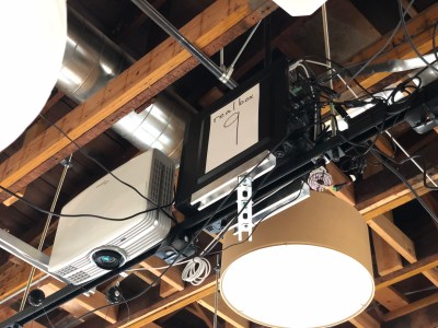
The new Real-Time HAT by InnoRoute adds IEEE1588 PTP support in hardware to a Raspberry Pi 4 nestled beneath. Based around a Xilinx Artix-7 FPGA and a handful of gigabit Ethernet PHY devices, the HAT acts as network-passthrough, adding accurate time-stamps to egress (outgoing) packets and stripping time-stamps from the ingress (incoming) side.
This hardware time-stamping involves re-writing Ethernet packets on-the-fly using specialised network hardware which the Raspberry Pi does not have. Yes, there are software-only 1588 stacks, but they can only get down to 10s of microsecond resolutions, unlike a hardware approach which can get down to 10s of nanoseconds.
1588 is used heavily for applications such as telecoms infrastructure, factory equipment control and anything requiring synchronisation of data-consuming or data-producing devices. CERN makes very heavy use of 1588 for its enormous arrays of sensors and control equipment, for all the LHC experiments. This is the WhiteRabbit System, presumably named after the time-obsessed white rabbit of Alice In Wonderland fame. So, if you have a large installation and a need for precisely controlling when stuff happens across it, this may be just the thing you’re looking for.
IEEE1588 PTP Synchronisation
The PTP client and master device ping a few messages back and forth between themselves, with the network time-stamper recording the precise moment a packet crosses the interface. These time-stamps are recorded with the local clock. This is important. From these measurements, the time-of-flight of the packet and offset of the local clock from the remote clock may be calculated and corrected for. In this way each client node (the hat) in the network will have the same idea of current time, and hence all network packets flowing through the whole network can be synchronised.
The beauty of the system is that the network switches, wiring and all that common infrastructure don’t need to speak 1588 nor have any other special features, they just need to pass along the packets, ideally with a consistent delay.
The Real-Time HAT configures its FPGA via SPI, straight from Raspberry Pi OS, with multiple applications possible, just by a change on the command line. It is possible to upload custom bitstreams, allowing the HAT to be used as a general purpose FPGA dev board should you wish to do so. It even stacks with the official PoE HAT, which makes it even more useful for hanging sensors on the end of a single wire.
Of course, if your needs are somewhat simpler and smaller in scale than a Swiss city, you could just hack a GPS clock source into a Raspberry Pi with a little soldering and call it a day.