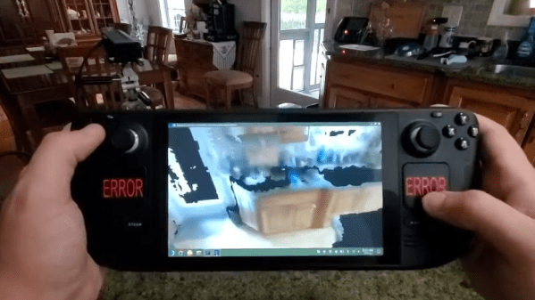
It may not be obvious, but Valve’s Steam Deck is capable of being more than just a games console. Demonstrating this is [Parker Reed]’s experiment in 3D scanning his kitchen with a Kinect and Steam Deck combo, and viewing the resulting mesh on the Steam Deck.
[Parker] runs the RTAB-Map software package on his Steam Deck, which captures a point cloud and color images while he pans the Kinect around. After that, the Kinect’s job is done and he can convert the data to a mesh textured with the color images. RTAB-Map is typically used in robotic applications, but we’ve seen it power completely self-contained DIY 3D scanners.
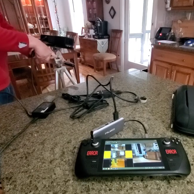
While logically straightforward, the process does require some finessing and fiddling to get it up and running. Reliability is a bit iffy thanks to the mess of cables and adapters required to get everything hooked up, but it does work. [Parker] shows off the whole touchy process, but you can skip a little past the five minute mark if you just want to see the scanning in action.
The Steam Deck has actual computer chops beneath its games console presentation, and we’ve seen a Steam Deck appear as a USB printer that saves received print jobs as PDFs, and one has even made an appearance in radio signal direction finding.
Continue reading “3D Scanning A Room With A Steam Deck And A Kinect”