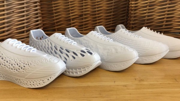
Hexagonal Mirror Array Hides Hidden Message

[Ben Bartlett] recently got engaged, and the proposal had a unique bit of help in the form of a 3D-printed hexagonal mirror array, whose mirrors are angled just right to spell out a message with the reflections. A small test is shown above projecting a heart, but the real deal was a bigger version reflecting the message “MARRY ME?” into sand at sunset. Who could say no to something like that? Luckily for all of us, [Ben] shared all the details of what went into designing and building such a thoughtful and fascinating device.

Mirrors on the 3D-printed array are angled just right to reflect light into a message.

Essentially, the array of mirrors works a bit like a projector. Each individual reflection can be can be thought of as a pixel, and the projected position of each can be modified by the precise angle of each mirror. With the help of some Python code, [Ben] calculated the exact angles needed to spell out “MARRY ME?” and generated the necessary 3D model. A smaller-scale test (shown in the header image above) was successful, and after that it was just a matter of printing the array and gluing on some mirrors.

Of course, that’s the short version. In practice there were quite a few troublesome issues that demonstrated the value of using early tests to discover hidden problems. For one thing, mirror angle and alignment is crucial, which meant that anything that could affect the shape of the array was a potential problem. Glue that expands or otherwise changes shape as it dries or cures could slightly change a mirror’s angle, so cyanoacrylate (CA) glue was preferred. However, the tiniest bit of CA glue will mess up a mirror’s surface in a hurry, so care was needed during assembly.

The gleaming hexagonal mirrors are reminiscent of the James Webb Space Telescope.

Another gotcha was when [Ben] suddenly realized, twenty hours into printing the final assembly, that the message needed to be reversed! As designed, the array he was printing would project “?EM YRRAM” and this wasn’t caught during testing because the test pattern (a heart) was symmetrical. Fortunately there was time to correct the error and start again, but it was close. [Ben]’s code has an optional visualization function, which was invaluable for verifying that things would actually turn out as expected. As it happens, the project took right up to the last minute to complete and there wasn’t quite time to check everything 100% before the big moment, but it all turned out alright. What’s life without a little mystery and danger, anyway?

The pictures are great, but you won’t regret taking the time to read through the project page (don’t miss the annotated Python code) because [Ben] goes into just the right level of detail. The end result looks fantastic, and makes an excellent keepsake with a charming story.

Those Bullet Effects In Terminator 2 Weren’t CGI

Remember Terminator 2? Guns were nearly useless against the murderous T-1000, played by Robert Patrick. Bullets fired at the “liquid metal” robot resulted only in a chrome-looking bullet splash that momentarily staggered the killing machine. The effects were done by Stan Winston, who died in 2008, but a video and short blurb shared by the Stan Winston School of Character Arts revealed, to our surprise and delight, that the bullet impact effects were not CGI.

How was this accomplished? First of all, Winston and his team researched the correct “look” for the splash impacts by firing projectiles into mud and painstakingly working to duplicate the resulting shapes. These realistic-looking crater sculpts were then cast in some mixture of foam rubber, and given a chromed look by way of vacuum metallizing (also known as vacuum deposition) which is a way of depositing a thin layer of metal onto a surface. Vacuum deposition is similar to electroplating, but the process does not require the object being coated to have a conductive surface.

These foam rubber splash patterns — which look like metal but aren’t — were deployed using a simple mechanical system. A variety of splashes in different sizes get individually compressed into receptacles in a fiberglass chest plate. Covering each is a kind of trapdoor, each held closed by a single pin on a cable.

To trigger a bullet impact effect, a wireless remote control pulls a cable, which pulls its attached pin, and the compressed splash pattern blossoms forth in an instant, bursting through pre-scored fabric in the process. Sadly there are no photos of the device itself, but you can see it in action in the testing video shared by the Stan Winston School, embedded below.

Continue reading “Those Bullet Effects In Terminator 2 Weren’t CGI”

This $0 Filament Drybox Needs Nearly No Parts

All 3D printer filament benefits from being kept as dry as possible, but some are more sensitive to humidity than others. The best solution is a drybox; a sealed filament container, usually with some desiccant inside. But in a pinch, [Spacefan]’s quick and dirty $0 drybox solution is at least inspiring in terms of simplicity.

The only added part is this 3D-printed fitting.

[Spacefan]’s solution uses a filament roll’s own packing materials and a single 3D-printed part to create a sealed environment for a single roll. The roll lives inside a plastic bag (potentially the same one it was sealed in) and filament exits through a small hole and 3D-printed fitting that also uses a bit of spare PTFE tubing. The box doubles as a convenient container for it all. It doesn’t have as much to offer as this other DIY drybox solution, but sure is simple.

While we appreciate the idea, this design is sure to put a lot of friction on the spool itself. It will be a lot of extra work to pull filament off the spool, which needs to turn inside a bag, inside a box, and that extra work will be done by the 3D printer’s extruder, a part that should ideally be working as little as possible. The re-use of materials is a great idea, but it does look to us like the idea could use some improvement.

What do you think? Useful in a pinch, or needs changes? Would adding a spindle to support the spool help? Let us know what you think in the comments.

Hardware Project Becomes Successful Product For Solo Developer

[Michael Lynch] has been a solo developer for over three years now, and has been carefully cataloguing his attempts at generating revenue for himself ever since making the jump to being self-employed. Success is not just hard work; it is partly knowing when the pull the plug on an idea, and [Micheal] has been very open about his adventures in this area. He shares the good news about a DIY project of his that ended up becoming a successful product, complete with dollar amounts and frank observations.

About a year ago, we covered a project he shared called TinyPilot, which is an effective KVM-over-IP device, accessible over the web, that could be built with about $100 worth of parts. [Micheal] found it to be a fun and useful project, and decided to see if he could sell kits. However, he admits he didn’t have high expectations, and his thoughts are probably pretty familiar to most hardware types:

I questioned whether there was a market for this. Why would anyone buy this device from me? It was just a collection of widely available hardware components.

Well, it turns out that he was onto something, and the demand for his device became immediately clear. He’s since given TinyPilot more features, an attractive case, and even provides a support plan for commercial customers. This is an excellent reminder that sometimes, what is being sold isn’t the collection of parts itself. Sometimes, what’s being sold is a solution to a problem people have, and those people are time-poor and willing to pay for something that just works.

It’s great to see [Michael] find some success as a solo developer, but his yearly wrap-up covers much more than just the success of TinyPilot as a product, so be sure to check it out if you’re at all interested in the journey of working for yourself.

An Emulator For OBP, The Spaceflight Computer From The 1960s

[David Given] frequently dives into retrocomputing, and we don’t just mean he refurbishes old computers. We mean things like creating a simulator and assembler for the OBP spaceflight computer, which was used in the OAO-3 Copernicus space telescope, pictured above. Far from being a niche and forgotten piece of technology, the On-Board Processor (OBP) was used in several spacecraft and succeeded by the Advanced On-board Processor (AOP), which in turn led to the NASA Standard Spaceflight Computer (NSSC-1), used in the Hubble Space Telescope. The OBP was also created entirely from NOR gates, which is pretty neat.

One thing [David] learned in the process is that while this vintage piece of design has its idiosyncrasies, in general, the architecture has many useful features and is pleasant to work with. It is a bit slow, however. It runs at a mere 250 kHz and many instructions take several cycles to complete.

Sample of the natural-language-looking programming syntax for the assembler. (Example from page 68 of the instruction set manual for the OBP.)

One curious thing about the original assembler was documentation showing it was intended to be programmed in a natural-language-looking syntax, of which an example is shown here. To process this, the assembler simply mapped key phrases to specific assembly instructions. As [David] points out, this is an idea that seems to come and go (and indeed the OBP’s successor AOP makes no mention whatsoever of it, so clearly it “went”.) Since a programmer must adhere to a very rigid syntax and structure anyway to make anything work, one might as well just skip dealing with it and write assembly instructions directly, which at least have the benefit of being utterly unambiguous.

We’re not sure who’s up to this level of detail, but embedded below is a video of [David] coding the assembler and OBP emulator, just in case anyone has both an insatiable vintage thirst and a spare eight-and-a-half hours. If you’d prefer just the files, check out the project’s GitHub repository.

Continue reading “An Emulator For OBP, The Spaceflight Computer From The 1960s”

Extracting Data From Smart Scale Gives Rube Goldberg A Run For His Money

[Kevin Norman] got himself a smart body scale with the intention of logging data for his own analysis, but discovered that extracting data from the device was anything but easy. It turns out that the only way to access data from his scale is by viewing it in a mobile app. Screen-scraping is a time-honored method of pulling data from uncooperative systems, so [Kevin] committed to regularly taking a full-height screenshot from the app and using optical character recognition (OCR) to get the numbers, but making that work was a surprisingly long process full of dead ends.

First of all, while OCR can be reliable, it needs the right conditions. One thing that ended up being a big problem was the way the app appends units (kg, %) after the numbers. Not only are they tucked in very close, but they’re about half the height of the numbers themselves. It turns out that mixing and matching character height, in addition to snugging them up against one another, is something tailor-made to give OCR reliability problems.

The solution for this particular issue came from an unexpected angle. [Kevin] was using an open-source OCR program called Tesseract, and joined an IRC community #tesseract to ask for advice after exhausting his own options. The bemused members of the online community informed [Kevin] that they had nothing to do with OCR; #tesseract was actually a community for an open-source 3D FPS shooter of the same name. But as luck would have it, one of the members actually had OCR experience and suggested the winning approach: pre-process the image with OpenCV, using cv2.findContours() to detect and create a bounding box around each element. If an element is taller than a decimal point but shorter than everything else, throw it out. With that done, there were still a few more tweaks required, but the finish line was finally in sight.

Now [Kevin] can use the scale in the morning, take a screenshot, and in less than half a minute the results are imported into a database and visualizations generated. The resulting workflow might look like something Rube Goldberg would approve of, but it works!

Raspberry Pi Reads What It Sees, Delights Children

[Geyes30]’s Raspberry Pi project does one thing: it finds arbitrary text in the camera’s view and reads it out loud. Does it do so flawlessly? Not really. Was it at least effortless to put together? Also no, but it does wonderfully illustrate the process of gluing together different bits of functionality to make something new. Also, [geyes30]’s kids find it fascinating, and that’s a win all on its own.

The device is made from a Raspberry Pi and camera and works by sending a still image from the camera to an optical character recognition (OCR) program, which converts any visible text in the image to its ASCII representation. The recognized text is then piped to the espeak engine and spoken aloud. Getting all the tools to play nicely took a bit of work, but [geyes30] documented everything so well that even a novice should be able to get the project up and running in an afternoon.

Sometimes a function like text-to-speech is an end result in and of itself. This was also true of another similar project: Magic Mirror, whose purpose was to tirelessly indulge children’s curiosity about language.

Seeing other projects come to life and learning about new tools is a great way to get new ideas, and documenting them helps cross-pollinate among creative types. Did something inspire you recently, or have you documented your own project? We want to hear about it and so do others, so let us know via the tips line!

Continue reading “Raspberry Pi Reads What It Sees, Delights Children”