A friend of ours once described computers as “high-speed idiots.” It was true in the 80s, and it appears that even with the recent explosion in AI, all computers have managed to do is become faster. Proof of that can be found in a story about using ASCII art to trick a chatbot into giving away the store. As anyone who has played with ChatGPT or its moral equivalent for more than five minutes has learned, there are certain boundary conditions that the LLM’s creators lawyers have put in place to prevent discussion surrounding sensitive topics. Ask a chatbot to deliver specific instructions on building a nuclear bomb, for instance, and you’ll be rebuffed. Same with asking for help counterfeiting currency, and wisely so. But, by minimally obfuscating your question by rendering the word “COUNTERFEIT” in ASCII art and asking the chatbot to first decode the word, you can slip the verboten word into a how-to question and get pretty explicit instructions. Yes, you have to give painfully detailed instructions on parsing the ASCII art characters, but that’s a small price to pay for forbidden knowledge that you could easily find out yourself by other means.
Author: Dan Maloney3373 Articles
A SPIF-fy Way Of Forming Metal
Thanks to 3D printing, most of us are familiar with the concept of additive manufacturing, and by extension, subtractive manufacturing. But what is it when you’re neither adding material nor taking it away to create something? Generally speaking, that’s called forming, and while there are tons of ways to do it, one you might not have heard of is single-point incremental forming (SPIF), and it’s pretty cool.
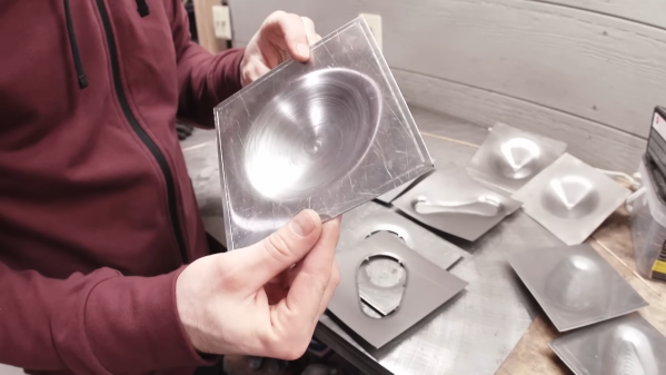
To explore SPIF as a method for making small parts, [Russell Makes] gave it a go on a small CNC mill. The idea is pretty simple, and the video below makes it pretty clear what’s going on. A forming tool is moved over a sheet metal blank that’s held very securely to the mill’s table. The tool has no cutting edges, just a smooth, hard, spherical tip — [Russell] made his own by brazing a carbide ball to a piece of drill rod. The tool is driven slightly into the blank along the Z-axis, while simultaneously tracing out a tool path in the XY plane. The tool spins, but very slowly; ideally, the spindle speed is controlled to keep a single point of contact with the metal as the tool works around its tool path. The tool steps downward incrementally, drawing the metal down with it as it forms the desired shape.
[Russell]’s experiments were pretty promising. He started with titanium sheet, which behaved pretty well except for some galling thanks to lack of lubrication. Aluminum and stainless worked pretty well too, at least for simple hemispherical and cone shapes. More complex shapes proved trickier, but with time he was able to figure out the correct speeds and feeds to keep the metal intact. The amount of tension built up in the metal is impressive, though, and is especially evident when cutting the finished part free from the blank.
Could this work with a hobbyist-grade machine? Possibly, but we’d be afraid that the forces involved might be a bit much for light-duty machines, especially in the Z-axis. And it’s a slow process, so it’s probably only good for one-offs and low-volume work. Once you’ve got a prototype, die stamping might be a more efficient way to go.
The Perils Of Return Path Gaps
The radio frequency world is full of mysteries, some of which seem to take a lifetime to master. And even then, it seems like there’s always something more to learn, and some new subtlety that can turn a good design on paper into a nightmare of unwanted interference and unexpected consequences in the real world.
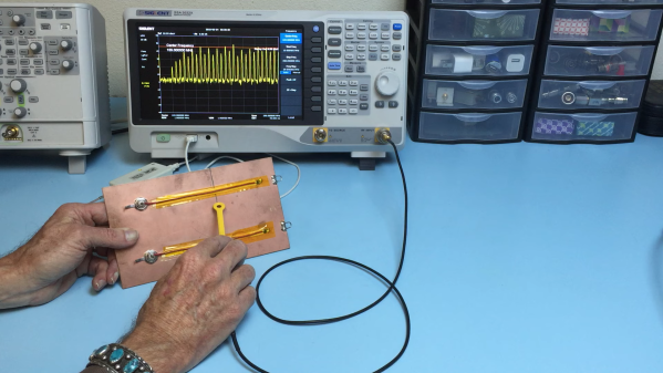
As [Ken Wyatt] aptly demonstrates in the video below, where you put gaps in return paths on a PCB is one way to really screw things up. His demo system is simple: a pair of insulated wires running from the center pins on BNC jacks and running along the surface of a piece of copper-clad board to simulate a PCB trace. The end of each wire is connected to the board’s ground plane through a 50 ohm resistor, with one wire running over a narrow slot cut into the board. A harmonics-rich signal is fed into each trace while an H-field EMC probe connected to a spectrum analyzer is run along the length of the trace.
With the trace running over the solid ground plane, the harmonics are plentiful, as expected, but they fall off very quickly away from the trace. But over on the trace with the gapped return trace it’s a far different story. The harmonics are still there, but they’re about 5 dBmV higher in the vicinity of the gap. [Ken] also uses the probe to show just how far from the signal trace the return path extends to get around the gap. And even worse, the gap makes it so that harmonics are detectable on the unpowered trace. He also uses a current probe to show how common-mode current will radiate from a long conductor attached to the backplane, and that it’s about 20 dB higher with the gapped trace.
Hats off to [Ken] for this simple explanation and vivid reminder to watch return paths on clock traces and other high-frequency signals. Need an EMC probe to check your work? A bit of rigid coax and an SDR are all you need. Continue reading “The Perils Of Return Path Gaps”
A Look Inside A 70-GHz Electromechanical Attenuator
It might not count as “DC to daylight,” but an electromechanical attenuator that covers up to 70 GHz is pretty close, and getting a guided tour of its insides is quite a treat.
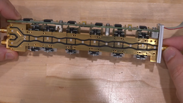
Perhaps unsurprisingly, this one comes to us from [Shahriar] at “The Signal Path,” where high-end gear most of us never get a chance to work with goes for one last hurrah after it releases the magic smoke. And indeed, that appears to be exactly what happened to the Rohde & Schwarz 75 dB step attenuator, a part that may have lived in the front end of one of their spectrum analyzers. As one would expect from such an expensive component, the insides have some pretty special engineering. The signal is carried through the five attenuation stages on a narrow strip of copper. Each stage uses a solenoid to move the strip between either a plain conductor or a small Pi pad with a specified attenuation. The attention to detail inside the cavity is amazing, with great care taken to maintain the physical orientation of the stripline to prevent impedance mismatches and unwanted reflections.
The Pi pads themselves are fascinating, too, especially under [Shahriar]’s super-duper microscope. All of them were destructively removed from the cavity before getting to him, but it’s still pretty clear what’s going on. That’s especially true with the 5-dB pad, which bears clear signs of the overload that brought on the demise of the whole attenuator. We suppose a repair would have been feasible if it had been just the one pad that needed replacement, but with all of them broken, it’s off to the scrap bin. Or to the recycler — there appears to be plenty of gold in there.
We thought this was a fantastic look under the covers of an exquisitely engineered part. Too bad it didn’t rate the [Shahriar] X-ray treatment, as this multimeter repair or this 60-GHz phased array did. Oh, well — maybe next time.
Continue reading “A Look Inside A 70-GHz Electromechanical Attenuator”
High-Voltage Fun With An Inexpensive Power Supply
It used to be that nearly every home had at least one decent high-voltage power supply. Of course, it was dedicated to accelerating electrons and slamming them into phosphors so we could bathe ourselves in X-rays (not really) while watching Howdy Doody. These days the trusty tube has been replaced with LEDs and liquid crystals, which is a shame because there’s so much fun to be had with tens of thousands of volts at your disposal.
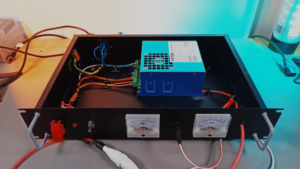
That’s the impetus behind this inexpensive high-voltage power supply by [Sebastian] over at Baltic Labs. The heavy lifting for this build is done by a commercially available power supply for a 50-watt CO2 laser tube, manufactured — or at least branded — by VEVOR, a company that seems intent on becoming the “Harbor Freight of everything.” It’s a bold choice given the brand’s somewhat questionable reputation for quality, but the build quality on the supply seems decent, at least from the outside. [Sebastian] mounted the supply inside a rack-mount case, as one does, and provided some basic controls, including the obligatory scary-looking toggle switch with safety cover. A pair of ammeters show current and voltage, the latter with the help of a high-voltage resistor rated at 1 gigaohm (!). The high-voltage feedthrough on the front panel is a little dodgy — a simple rubber grommet — but along with the insulation on the high-voltage output lead, it seems to be enough.
The power supply’s 30 kV output is plenty for [Sebastian]’s current needs, which from the video below appear to mainly include spark gap experiments. He does mention that 50 kV commercial supplies are available too, but it would be tough to do that for the $150 or so he spent on this one. There are other ways to go, of course — [Niklas] over at Advanced Tinkering recently shared his design for a more scratch-built high-voltage supply that’s pretty cool too. Whatever you do, though, be careful; we’ve been bitten by a 50 kV flyback supply before and it’s no joke.
Continue reading “High-Voltage Fun With An Inexpensive Power Supply”
Custom Library Rescues Good LoRa Hardware From Bad Firmware
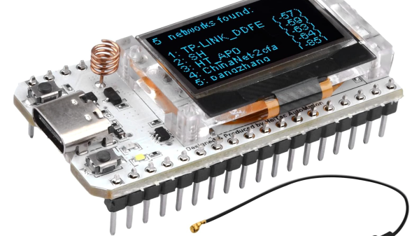
The range of hardware that comes on some dev boards these days is truly staggering. Those little LoRa boards are a prime example — ESP32 with WiFi and Bluetooth, a transceiver that covers a big chunk of the UHF band, and niceties like OLED displays and plenty of GPIO. But the firmware and docs? Well, if you can’t say something nice, don’t say anything at all. Or better yet, just roll your own.
Of course that doesn’t hold true for all the LoRa dev boards on the market, but [Rop] certainly found it to be the case for the Heltec HTIT-WB32LA. This board has all the bells and whistles and would be perfect for LoraWAN and Meshtastic applications, but it needed a little help getting it over the line. [Rop]’s contribution to this end is pretty comprehensive and is based on his fork of the RadioLib library, which incorporates a library that greatly reduces wear on the ESP32’s flash memory. In addition to full radio support, the library supports all the hardware on the board from the pushbutton to the display, power management and battery charging, and of course the blinkenlights.
[Jop] includes quite a few example applications, from the bare minimum needed to get the board spun up to a full-blown spectrum analyzer. It’s a nice piece of work, and a great give-back to the LoRa community. And if you want to put one of these modules to work, you’re certainly in the right place. We’ve got everything from LoRaWAN networks to the magic of Meshtastic, so take your pick and get hacking.
A 555-Shaped Discrete Component 555
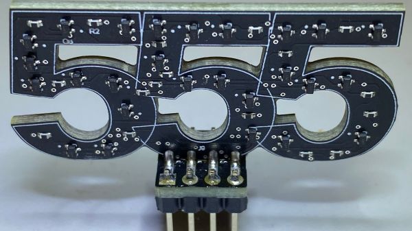
While the “should have used a 555” meme is strong around these parts, we absolutely agree with [Kelvin Brammer]’s decision to make this 555-shaped plug-in replacement for the 555 timer chip using discrete parts, rather than just a boring old chip.
As [Kelvin] relates, this project started a while back as an attempt to both learn EDA and teach students about the inner workings of the venerable timer chip. The result was a 555-equivalent circuit on a through-hole PCB, with the components nicely laid out into the IC’s functional blocks. As a bonus, the PCB was attached to an 8-pin header which could be plugged right in as a direct replacement for the chip.
Fast forward a few years, and [Kelvin] needed to learn yet another EDA package; what better way than to repeat the 555 project? It was also a good time to step into SMD design, as well as add a little zazzle. While the updated circuit isn’t as illustrative of the internal arrangement of the 555, the visual celebration of the “triple nickel” is more than worth it. And, just like the earlier version, this one has a header so you can just plug and chug — with style.
Want to know how the 555 came to be? We’ve covered that. You can also look at some basic 555 circuits to put your 555-shaped 555 to work. We’ve even seen a vacuum tube 555 if that’s more your thing.


