Among all the timepieces that we feature here at Hackaday, surprisingly we bring you relatively few clocks. That might seem an incomprehensible statement given the plethora of, well, clocks, that appear here, but it’s one that hinges upon the type of clock. Electronic clocks of extreme skill, complexity, and beauty, yes, but traditional mechanical clocks? Not so many.
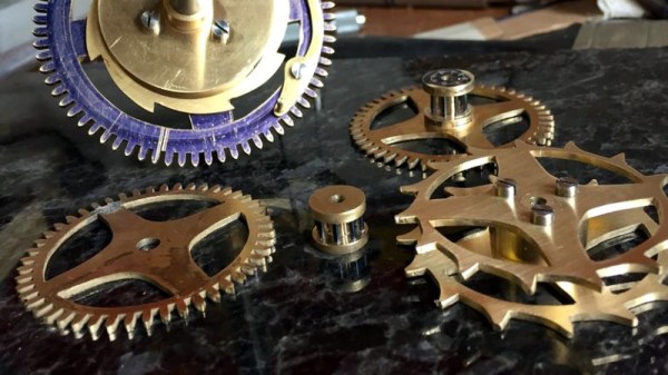
So [Thonemeister]’s wall-mounted brass alarm clock was a welcome sight on our tips line, and his write-up is a fascinating exposition of the path taken by a novice clockmaker on their first build. He starts by describing his workshop, then steps methodically through each of the constituent parts of the clock.
We see the frame, escapement mechanism, gears, and movement taking shape, and we learn something about clockmaker’s tools from the pitfalls he encountered. He was a complete lathe novice at the start of this build, and it’s fun to follow along with his learning curve. As we see thed finished clock taking shape, we even get to see the little touches like forming the hooks for the weights. He bought the bell for the clock off-the-shelf, not wishing to expend the considerable piece of brass stock it would have taken to machine it himself. But for the most part, this is an engaging scratch build you won’t want to miss.
Many of us will never make a traditional clock. But that need not stop us finding the work that goes into one an extremely fascinating read. We have more for you if this has whetted your appetite: you’ll be interested in the escapement mechanism, and if brass is a bit much, how about wood?

 The aim of the project was to demonstrate the feasibility of a rover exploring a planetary surface, picking up, and examining rocks. Lest you imagine a billion dollar budget for gleaming rover prototypes, it’s fair to say that this was to be achieved with considerably more modest means. The rover was a repurposed unit that had previously been used for remote handling of hazardous chemicals, and the project’s computer was an extremely obsolete DEC PDP-1.