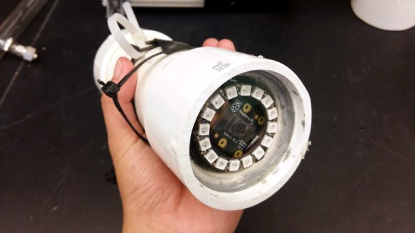
We are surrounded by sensors for all forms of environmental measurement, and a casual browse through an electronics catalogue can see an experimenter tooled up with the whole array for a relatively small outlay. When the environment in question is not the still air of your bench but the turbulence, sand, grit, and mud of a sea floor, that pile of sensors becomes rather useless. [Ellie T] has been addressing this problem as part of the study of hypoxia in marine life, and part of her solution is to create an underwater camera by encasing a Raspberry Pi Zero W and camera in a sturdy enclosure made from PVC pipe. She’s called the project LoBSTAS, which stands for Low-cost Benthic Sensing Trap-Attached System.
The housing is simple enough, the PVC has a transparent acrylic disk mounted in a pipe coupler at one end, with the seal being provided at the other by an expansion plug. A neopixel ring is mounted in the clear end, with the Pi camera mounted in its centre. Meanwhile the Pi itself occupies the body of the unit, with power coming from a USB battery bank. The camera isn’t the only sensor on this build though, and Atlas Scientific oxygen sensor completes the package and is mounted in a hole drilled in the expansion plug and sealed with silicone sealant.
When you have a complex task that would sap the time and energy of your microprocessor, it makes sense to offload it to another piece of hardware. We are all used to this in the form of the graphics chipsets our computers use — specialised processors whose computing power in that specific task easily outshines that of our main CPU. This offloading of tasks is just as relevant at the microcontroller level too. One example is the EM Microelectronics EM7180 motion co-processor. It takes input from a 3-axis gyroscope/accelerometer and magnetometer, acting for all intents and purposes as a fit-and-forget component. Given an EM7810, your host can determine its heading and speed at a simple command, with no need for any hard work.
[Kris Winer] used the EM7810, but frustrated at its shortcomings decided to create a more versatile alternative. The result is a small PCB holding a Maxim MAX32660 ARM Cortex M4F microcontroller and the relevant sensors, with the MAX32660’s increased power and integrated flash easily eclipsing the EM7810.
As a design exercise it’s an interesting read even if you have no need for one. His write-up goes into detail on the state of the motion coprocessor art, and then looks carefully at pushing the limits of what is possible using an inexpensive PCB fabrication house such as OSH Park — you can get this chip as a Wafer-Level Package (WLP) which is definitely off-limits. Even with the TQFN-24 he picked though, the result is a tiny board and we’re happy to see it as an entry in the Return of the Square Inch Project!
It is perhaps surprising how few projects like this one make it into our sphere, as a community we tend to focus upon making one processor do all the hard work. But with the ready availability of inexpensive and powerful devices, perhaps this is an approach that we should reconsider.
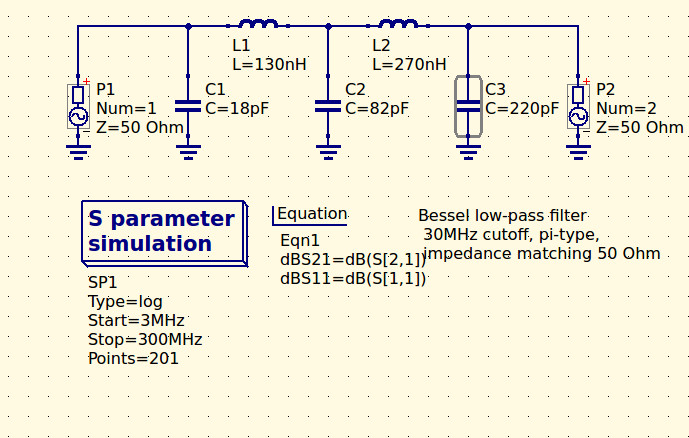
If you are in any way connected with radio, you will have encountered the low pass filter as a means to remove unwanted harmonics from the output of your transmitters. It’s a network of capacitors and inductors usually referred to as a pi-network after the rough resemblance of the schematic to a capital Greek letter Pi, and getting them right has traditionally been something of a Black Art. There are tables and formulae, but even after impressive feats of calculation the result can often not match the expectation.
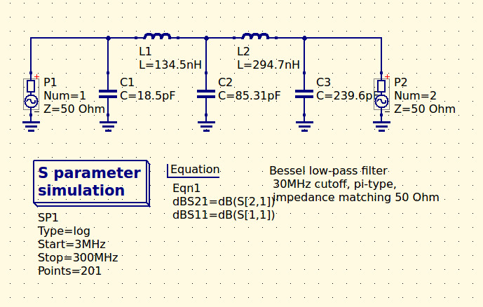
The 30MHz low-pass filter, as QUCS delivered it.
Happily as with so many other fields, in recent decades the advent of affordable high-power computing has brought with it the ability to take the hard work out of filter design, Simply tell some software what the characteristics of your desired filter are, and it will do the rest. The results are good, and anyone can become a filter designer, but as is so often the case there remains a snag. The software calculates ideal inductances and capacitances for the desired cut-off and impedance, and in selecting the closest preferred values we modify the characteristics of the result and possibly even ruin our final filter. So it’s worth taking a look at the process here, and examining the effect of tweaking component values in this way.
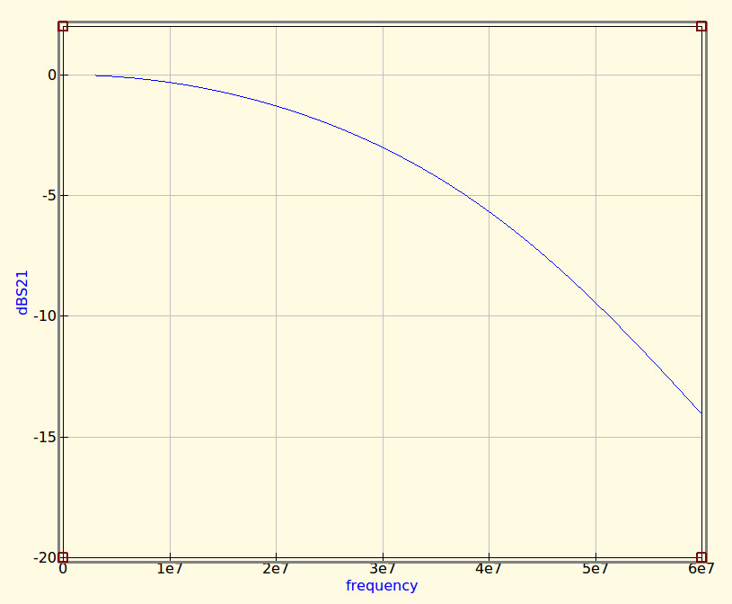
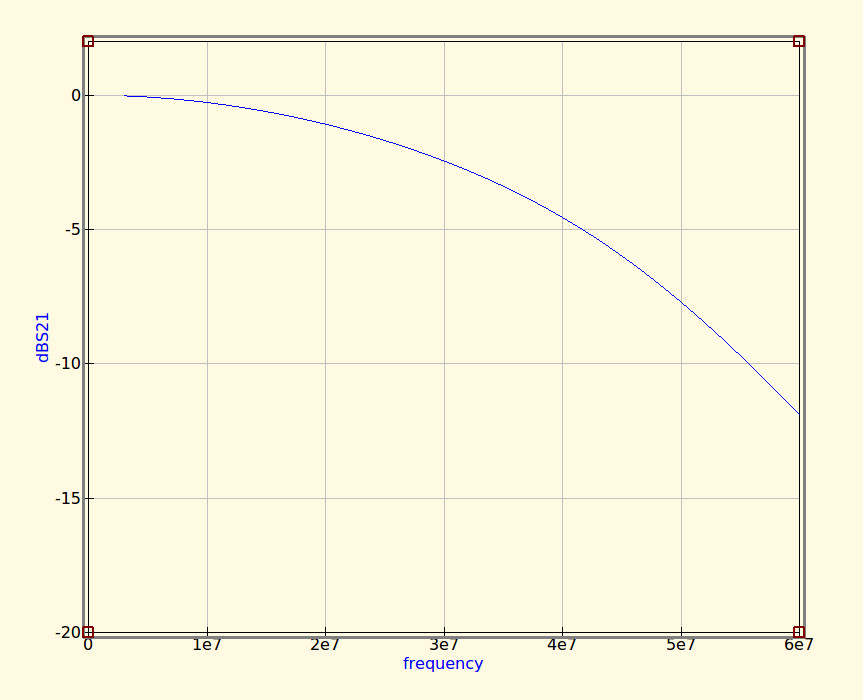
The idealised graph produced by QUCS for our filter.
The filter we’re designing is simple enough, a 5th-order Bessel filter, and the software is the easy-to-use QUCS package on an Ubuntu Linux machine. Plug in the required figures and it spits out a circuit diagram, which we can then simulate to show a nice curve with a 3dB point right on 30MHz. It’s an extremely idealised graph, and experience has taught me that real-world filters using these designs have a lower-frequency cut-off point, but for our purposes here it’s a good enough start.
As previously mentioned, the component values are not preferred ones from a commercially available series, so I can’t buy them off the shelf. I can wind my own inductors, but therein lies a whole world of pain of its own and I’d rather not go there. RS, Mouser, Digikey, Farnell et al exist to save me from such pits of electronic doom, why on earth would I do anything else but buy ready-made?
My revised filter circuit with off-the-shelf component values.
So each of the components in the above schematic needs moving up or down a little way to a preferred value. What effect will that have on the performance of my filter? Changing each value and re-running the simulation shows us the graph changing subtly each time, and it can sometimes be a challenge to adjust them without destroying the filter entirely. Particularly with the higher-order filters with more components in the network you can observe the effect of individual components on the gradient at different parts of the graph, but as a rule of thumb making values higher reduces the cut-off frequency and making them lower increases it. In my case I always pick higher values for that reason: my nearest harmonic I wish to filter is at double the frequency so I have quite some headroom to play with.
The revised curve from the filter with preferred values.
Having replaced my component values with preferred ones I can run the simulation again, and I can see from the resulting graph that I’ve been quite fortunate in not damaging its characteristics too much. As expected the cut-off frequency has shifted up a little, but the same curve shape has been preserved without any ripples appearing or it being made shallower.
If I were using this filter with a real transmitter I would ensure that I designed it with a cut-off at least a quarter higher than the transmission frequency. In practice I find the cut-off to be sharper and lower than the simulation leads one to expect, and for example, were I to use this one with a 30 MHz transmitter I’d find it attenuated the carrier by more than I’d consider acceptable. It must also be admitted that changing the component values in this way will also change the impedance of the filter from the calculated 50 ohms, however in practice this does not seem to be significant enough to cause a problem as long as the value changes are modest.
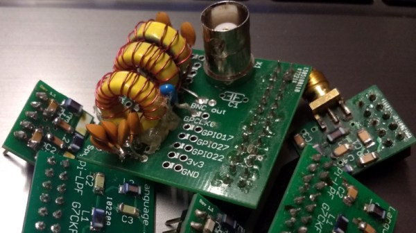
We haven’t made this filter, but in the past we’ve featured another one I did make, and by coincidence it was in the same frequency range. When I wrote a feature on automating oscilloscope readings, the example I used was the characterisation of a 7th-order 30 MHz low-pass filter. It might even be one of the ones in the header image, pulled from my random bag of filter boards for the occasion.
We feature hacks on this site of all levels of complexity. The simplest ones are usually the most elegant of “Why didn’t I think of that!” builds, but just occasionally we find something that is as much a bodge as a hack, a piece of work the sheer audacity of which elicits a reaction that has more of the “How did they get away with that! ” about it.
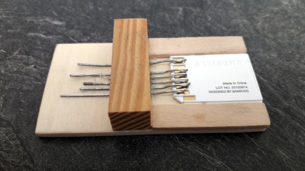
Such a moment comes today from [Robinlol], who has made an SD card socket. Why would you make an SD card socket when you could buy one is unclear, beyond that he didn’t want to buy one on an Arduino shield and considered manufacture his only option. Taking some pieces of wood, popsicle sticks, and paperclips, he proceeded to create a working SD card of such bodgeworthy briliance that even though it is frankly awful we still can’t help admiring it. It’s an SD card holder, and despite looking like a bunch of bent paperclips stuck in some wood, it works. What more could you want from an SD card holder?
Paperclips are versatile items. If an SD card holder isn’t good enough, how about using them in a CNC build?
There is one thing that unites almost every computer and logic circuit commonly used in the hardware hacking and experimentation arena. No matter what its age, speed, or internal configuration, electronics speak to the world through logic level I/O. A single conductor which is switched between voltage levels to denote a logic 1 or logic zero. This is an interface standard that has survived the decades from the earliest integrated circuit logic output of the 1960s to the latest microcontroller GPIO in 2018.
The effect of this tried and true arrangement is that we can take a 7400 series I/O port on an 8-bit microcomputer from the 1970s and know with absolute confidence that it will interface without too much drama to a modern single-board computer GPIO. When you think about it, this is rather amazing.
It’s tempting to think then that all logic level outputs are the same, right? And of course they are from a certain viewpoint. Sure, you may need to account for level shifting between for example 5V and 3.3V families but otherwise just plug, and go, right? Of course, the real answer isn’t quite that simple. There are subtle electrical differences between the properties of I/O lines of different logic and microcontroller families. In most cases these will never be a problem at all, but can rear their heads as edge cases which the would-be experimenter needs to know something about.
There is an air of excitement among the hackerspaces of Europe, because this month is hacker camp season. In Denmark they have Bornhack beginning on Thursday, in Italy IHC was held earlier in the month, while here in the UK we are looking forward to Electromagnetic Field. We’re excited be at Eastnor Castle for Electromagnetic Field at the cusp of August and September for several days under canvas surrounded by our community’s best and brightest work. We’ll even have a Hackaday Readers’ Village this year!
If you’ve never been to a hacker camp before, this is one that’s not to be missed. Technically this is camping, but where every structure from the smallest tent upwards has mains power and gigabit Ethernet. It’s the equivalent of a music festival if you replace the music with technology and other cool stuff from our world. There are talks on a huge variety of fascinating subjects, the chance to see up close some of the things you’ll have read about here on Hackaday, and best of all, a significant proportion of Europe’s hackerspace communities all together in one place. They are a uniquely stimulating and exciting environment.
We are fortunate enough to have a huge choice of single-board computers before us, not just those with a bare-metal microcontroller, but also those capable of running fully-fledged general purpose operating systems such as GNU/Linux. The Raspberry Pi is probably the best known of this latter crop of boards, and it has spawned a host of competitors with similarly fruity names. With an entire cornucopia to choose from, it takes a bit more than evoking a berry to catch our attention. The form factors are becoming established and the usual SoCs are pretty well covered already, show us something we haven’t seen before!
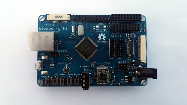
[Marcel Thürmer] may have managed that feat, with his Blueberry Pi. On the face of it this is just Yet Another SBC With A Fruity Pi Name, but what caught our attention is that unlike all the others, this is one you can build yourself if you want. It’s entirely open-source, but it differs from other boards that release their files to the world in that it manages to keep construction within the realm of what is possible on the bench rather than the pick-and-place. He’s done this by choosing an Alwinner V3, an SoC originally produced for the action camera market that is available in a readily-solderable TQFP package. It’s a choice that has allowed him to pull off another constructor-friendly feat: the board is only two layers, so it won’t break the bank to have it made.
It’s fair to say that the Allwinner V3 (PDF) isn’t the most powerful of Linux-capable SoCs, but it has the advantage of built-in RAM to avoid more tricky soldering. With only 64Mb of memory, it’s never going to be a powerhouse, but it does pack onboard Ethernet, serial and parallel camera interfaces, and audio as well as the usual interfaces you’d expect. There is no video support on the Blueberry Pi, but the chip has LVDS for an LCD panel, so it’s not impossible to imagine something could be put together. Meanwhile, all you need to know about the board can be found on its GitHub repository. There is no handy OS image to download, u-boot instructions are provided to build your own. We suspect if you’re the kind of person who is building a Blueberry Pi though this may not present a problem to you.
We hope the Blueberry Pi receives more interest, develops a wider community, and becomes a board with a solid footing. We like its achievement of being both a powerful platform and one that is within reach of the home constructor, and we look forward to it being the subject of more attention.