Some of the hacks we feature are modifications of existing devices, others are ground-up builds of entirely new ones. And then there are the experiments, things that have to be worth trying because they just might work. In this final category we have [Matt]’s work with UV sensitive plastic to form the basis of a simple persistent display, which has created something best described as a proof-of-concept that shows promise, and definitely proves that he had an idea very much worth trying.
The idea makes use of a plastic that changes colour from white to purple when exposed to UV light. He 3D printed a waffle-like structure to locate over a 3×3 grid of UV LEDs, which he could then illuminate under the control of an Arduino Mini Pro. A short illumination changes the colour of the plastic above it, creating a “pixel” that persists for several seconds. In this he has created a working proof of concept for a very simple 3×3 matrix display, albeit rather an unwieldy one. The advantage the idea offers is that a relatively long time of display can be achieved for a relatively short LED illumination, giving a potential for power saving.
The proof-of-concept itself isn’t particularly useful, but from this idea it’s possible a larger display could be practically made. An array of surface-mount LEDs could perhaps illuminate a larger array of plastic to a greater resolution, it’s definitely an idea that was worth trying, and which shows promise for further pursuit. If you’d like to see it in action he’s posted a video, which we’ve placed below the break.
Raspberry Pi laptops are not an uncommon sight, as many hardware enthusiasts have shoehorned the tiny board behind LCD panels into home-made cases.
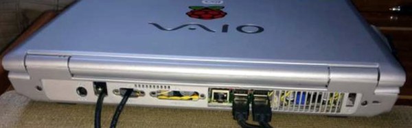
[Frank Adams] has created one of the best Pi laptops we’ve ever seen, (for which we suggest you skip straight to the PDF). He’s removed the guts from an aged Sony VAIO laptop and replaced it with the fruity computer, alongside a Teensy to handle VAIO keyboard, buttons, and LED I/O via the Pi USB port. An M.NT68676 video board interfaces the VAIO display to the Pi HDMI, and a USB to SATA cable is connected to a 240Gb solid state hard drive. The laptop’s Wi-Fi antenna is routed to the Pi via a soldered on co-axial connector, and there is also a real-time clock board. There are a few rough edges such as a USB cable that could be brought inboard, but it’s otherwise well-integrated into the case. His write-up is a very comprehensive PDF, that should serve as a good primer to anyone else considering such a laptop conversion.
The result is a laptop that looks for all the world like a commercially produced machine, yet that is also a Raspberry Pi. In a strange way, a Sony laptop is an apt homecoming for the board from Cambridge, because other than red soldermask or very early Chinese-made models, all Raspberry Pi boards are made in a Sony factory in Wales. Whatever the donor laptop though, this is definitely a step above the run-of-the-mill Pi laptops. To see its competition, take a look at this very ugly machine with a bare LCD panel, or this laser-cut sandwich laptop.
Are you reading this on a machine running a GNU/Linux distribution? A Windows machine? Or perhaps an Apple OS? It doesn’t really matter, because your computer is probably running MINIX anyway.
There once was a time when microprocessors were relatively straightforward devices, capable of being understood more or less in their entirety by a single engineer without especially God-like skills. They had buses upon which hung peripherals, and for code to run on them, one of those peripherals had better supply it.
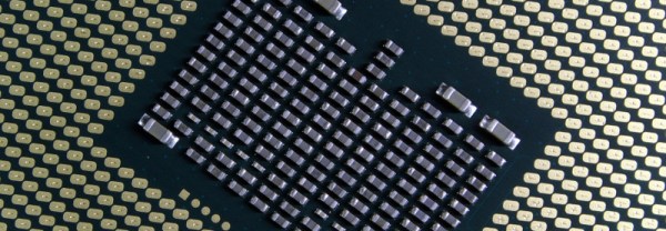
A modern high-end processor is a complex multicore marvel of technological achievement, so labyrinthine in fact that unlike those simple devices of old it may need to contain a dedicated extra core whose only job is to manage the rest of the onboard functions. Intel processors have had one for years, it’s called the Management Engine, or ME, and it has its own firmware baked into the chip. It is this firmware, that according to a discovery by [Ronald Minnich], contains a copy of the MINIX operating system.
If you are not the oldest of readers, it’s possible that you may not have heard of MINIX. Or if you have, it might be in connection with the gestation of [Linus Torvalds]’ first Linux kernel. It’s a UNIX-like operating system created in the 1980s as a teaching aid, and for a time it held a significant attraction as the closest you could get to real UNIX on some of the affordable 16-bit desktop and home computers. Amiga owners paid for copies of it on floppy disks, it was even something of an object of desire. It’s still in active development, but it’s fair to say its attraction lies in its simplicity rather than its sophistication.
It’s thus a worry to find it on the Intel ME, because in that position it lies at the most privileged level of access to your computer’s hardware. Your desktop operating system, by contrast, sees the hardware through several layers of abstraction in the name of security, so a simple OS with full networking and full hardware access represents a significant opportunity to anyone with an eye to compromising it. Placing tinfoil hats firmly on your heads as the unmistakable thwop of black helicopters eases into the soundscape you might claim that this is exactly what they want anyway. We would hope that if they wanted to compromise our PCs with a backdoor they’d do it in such a way as to make it a little less easy for The Other Lot. We suspect it’s far more likely that this is a case of the firmware being considered to be an out-of-sight piece of the hardware that nobody would concern themselves with, rather than a potential attack vector that everyone should. It would be nice to think that we’ll see some abrupt updates, but we suspect that won’t happen.
When men were men, and oscilloscopes were oscillographs.
Do you remember your first oscilloscope? Maybe we have entered the era in which younger readers think of a sleek model with an LCD screen, but for the slightly older among us the image that will come to mind is likely to be a CRT-based behemoth. Mine was a 2MHz bandwidth Cossor from the 1950s, wildly outdated by the 1980s, but it came to me at no cost. It proudly proclaims itself as a “Portable Oscillograph”, but requires its owner to be a weightlifter to move it. I still have it, as a relic and curio.
For most of us a new ‘scope is still a significant investment. Even affordable current models such as the extremely popular Rigol instruments are likely to cost several hundred dollars, but offer measurement functions undreamed of by those 1950s engineers who would have looked on the Cossor as an object of desire.
Oscilloscope buyers on a budget may not have the cash for a Rigol, a Hantek, or any of the other affordable ‘scopes. Someone starting on the road of electronic engineering can scout around for a cheap or free second-hand CRT model, but thanks to the ever advancing march of technology they also have another option. Modern microprocessors and microcontrollers have analogue-to-digital converters and processor cores that are fast enough to provide the functions of a simple oscilloscope, and to that end a variety of very cheap ‘scopes and ‘scope kits have come on the market. These invariably have a rather small LCD screen and a relatively low bandwidth, but since they can be had for almost pocket-money prices their shortcomings can be overlooked in the name of value. It’s been a matter of curiosity for some time then: are these instruments any good? For around £16 ($21) and the minor effort of an online order from China, we decided to find out.
If you look at most stockists of electronic kits these days, you are likely to find an oscilloscope kit in their range. These are volume produced in China, and the same design trends appear across different models. You can buy surface mount or through-hole, and most of them feature a bare board with maybe a piece of laser-cut Perspex standing in for a case. There are one or two models appearing that come with a case though, and it was one of these that we ordered. The JYE Tech DSO150 is a single-channel ‘scope with a 2.4″ 320×240 pixel colour LCD screen and a 200kHz bandwidth. Its specification is typical of the crop of similar kits, though its smart case sets it apart and made it an easy choice.
In the Box
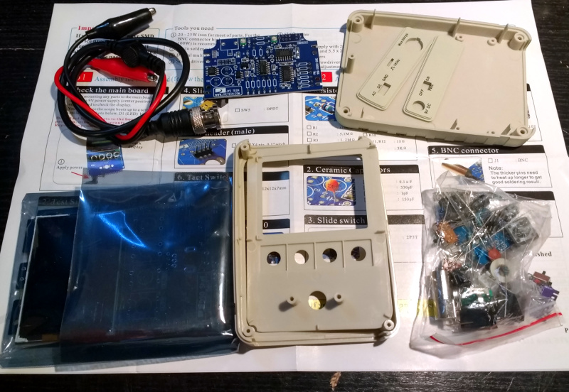
We ordered one, and when it arrived, it was packed in a small cardboard carton that had suffered some crushing in transit, but had protected the internal contents well enough that no harm had been done. A layer of foam protected the LCD, and the case parts appeared rigid enough to protect the rest of the components. There was a bag of discretes, the case parts, two PCBs, a test lead with crocodile clips, and two pages of instructions.
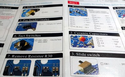
When looking at a kit, it’s best to start with the instructions, because no matter the quality of the kit itself it is the quality of the instructions that make or break a kit. If you can’t build it then it doesn’t matter how good it might be, it’s effectively junk.
The DSO150 instructions are two sheets of high quality double-sided colour print, with the emphasis on pictures rather than words, The front page introduces the kit and gives a quick soldering guide, then the next two pages step through each stage of construction. The final page has basic instructions for use, specification, and a troubleshooting guide. Our kit had all surface-mount parts already fitted, if we’d known the kit could also be had with SMD parts to fit we’d have bought that version instead.
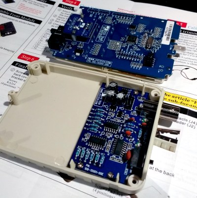
Inside the DSO100.
The instruction steps are long on images and short on text, but there are sometimes few cues as to where the component in question lies on the board. Sometimes some careful examination of board and picture is necessary to ensure correct placement. The first step though doesn’t involve any soldering, wire the main board up to a 9V supply, and watch the LCD boot into the oscilloscope software. There is support via a forum on the JYE Tech website, we presume you’d go there if it failed to boot out of the box. A 9V PSU isn’t included, you’ll need to find one with a 2.1mm centre positive plug. Fortunately a suitable candidate was in the box of wall warts here, formerly being used by a router.
The main board assembly is straightforward enough, being the assembly of larger through-hole parts such as switches and connectors. The analogue board has a brace of small through-hole resistors and ceramic capacitors to fit, of these the resistors were of the tiny variety which made distinguishing between some of their colour stripes a little difficult. Bring your multimeter to check. There is a BNC connector that requires significant heat on there too, so make sure you have a suitably beefy iron to hand. Finally there is a small board for the rotary encoder, then the front of the case can be assembled to the main board, the analogue board attached, and the ‘scope set up. Verify on-board voltages, attach the test clip to the calibration output and adjust the compensation capacitors for a square wave, and the rest of the case can be added to complete the unit.
Functionality
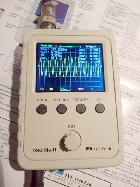
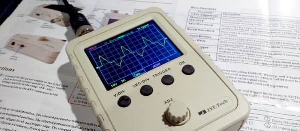
The DSO150 showing the upper end of its bandwidth.
In use, the DSO150 makes a simple and straightforward enough oscilloscope. The usual volts/division and timebase selection is easy enough, and the various trigger modes can quickly be selected. If you’ve used an oscilloscope before then you will have no problems getting started with it. But of course, the DSO150 isn’t just a simple oscilloscope, it’s a digital storage ‘scope. And with 1024 sampling points it can do the usual storage ‘scope thing of allowing the user to examine a stored waveform in great detail, scrolling back and forth through the stored points. Here the instruction sheet falls short, not mentioning that a double tap on the V/div or Sec/div buttons allows you to scroll.
Connecting the signal generator to our DSO150 allowed the exploration of its bandwidth. The claimed 200kHz is pretty spot-on, winding the signal generator far beyond that point showed a tail-off in displayed amplitude. Also the minimum 10µS per division limits the usefulness of a waveform display at these frequencies.
The DSO150 is supplied with a short test lead terminated in a pair of crocodile clips. This is somewhat less useful than the oscilloscope probes we’re used to, though happily it can also be used with a standard 1x/10x probe. Looking at the square wave on the test terminal through a standard probe reveals a sharp corner on the waveform, so there seems not to be any problems between the compensation on-board and that in the probe. It’s likely that either the DSO150 here will be used with a standard probe, or that the crocodile clip will swiftly be replaced with a probe of some kind.
Closing Thoughts
So then, the JYE Tech DSO150 oscilloscope kit. A nice little ‘scope within the limitations of the STM32F103C8 microcontroller that drives it. If you can put up with a 200kHz bandwidth and a 50V peak input voltage then it’s a useful pocket instrument. Its calibration will depend on the STM’s crystal and voltage reference, but as with the rest of its specification, when you consider its pocket-money price those become minor considerations. Add in that its software is open-source, and you have a very nice platform indeed. If we wanted to nitpick we’d ask for a battery compartment and a proper probe, but since both of those would put up the price we wouldn’t make too much noise about it. If you need a pocket ‘scope to supplement your bench scope when working on lower frequencies, or if you have a youngster in the family looking for their first ‘scope, buy one! Our review unit will definitely see some use rather than gathering dust.
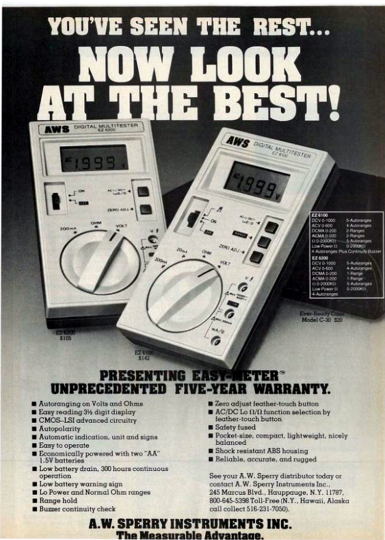
If you were to ask a random Hackaday reader what their most fundamental piece of electronic test equipment was, it’s likely that they would respond with “multimeter”. If you asked them to produce it, out would come a familiar item, a handheld brick with a 7-segment LCD at the top, a chunky rotary selector switch, and a pair of test probes. They can be had with varying quality and features for anything from a few dollars to a few hundred dollars, though they will nearly all share the same basic set of capabilities. Voltage in both AC and DC, DC current, resistance from ohms to mega ohms, and maybe a continuity tester. More expensive models have more features, may be autoranging, and will certainly have better electrical safety than the cheaper ones, but by and large they are a pretty standard item.
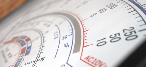
If Hackaday had been around forty years ago and you’d asked the same question, you’d have had a completely different set of multimeters pulled out for your inspection. Probably still a handheld brick with the big selector switch, but instead of that LCD you’d have seen a large moving-coil meter with a selection of scales for the different ranges. It would have done substantially the same job as the digital equivalent from today, but in those intervening decades it’s a piece of equipment that’s largely gone. So today I’m going to investigate moving coil multimeters, why you see them a lot less these days than you used to, and why you should still consider having one in your armoury. Continue reading “Why You Shouldn’t Quite Forget The Moving Coil Multimeter”→
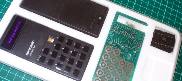
Last month we touched upon the world of 1970s calculators with a teardown of a vintage Sinclair, and in the follow-up were sent an interesting link: a review of a classic Sinclair calculator kit from [John Boxall]. It’s a few years old now, from 2013, but since it passed us by at the time and there was clearly some interest in our recent teardown, it’s presented here for your interest.
It seems odd in 2017 that a calculator might be sold as a kit, but when you consider that in the early 1970s it would have represented an extremely expensive luxury purchase it makes some sense that electronics enthusiasts who were handy with a soldering iron might consider the cost saving of self-assembly to be worthwhile. The £24.95 price tag sounds pretty reasonable but translates to nearly £245 ($320) in today’s terms so was hardly cheap. The calculator in question is a Sinclair Cambridge, the arithmetic-only predecessor to the Sinclair Scientific we tore down, and judging by the date code on its display driver chip it dates from September 1974.
As a rare eBay find that had sat in storage for so long it was clear that some of the parts had suffered a little during the intervening years. The discrete components were replaced with modern equivalents, including a missing 1N914 diode, and the display was secured in its flush-fitting well in the board with wire links. The General Instrument calculator chip differs from the Texas Instruments part used in the Scientific, but otherwise the two calculators share many similarities. A full set of the notoriously fragile Sinclair battery clips are in place, with luck they’ll resist the urge to snap. A particularly neat touch is the inclusion of a length of solder and some solder wick, what seems straightforward to eyes used to surface-mount must have been impossibly fiddly to those brought up soldering tube bases.
The build raises an interesting question: is it sacrilege to take a rare survivor like this kit, and assemble it? Would you do it? We’d hesitate, maybe. But having done so it makes for a fascinating extra look at a Sinclair Cambridge, so is definitely worth a read. If you want to see the calculator in action he’s posted a video which we’ve put below the break, and if you need more detail including full-resolution pictures of the kit manual, he’s put up a Flickr gallery.
When writing a recent piece about Reverse Polish Notation, or RPN, as a hook for my writing I retrieved my Sinclair Scientific calculator from storage. This was an important model in the genesis of the scientific calculator, not for being either a trailblazer or even for being especially good, but for the interesting manner of its operation and that it was one of the first scientific calculators at an affordable price.
I bought the calculator in a 1980s rummage sale, bodged its broken battery clip to bring it to life, and had it on my bench for a few years. Even in the early 1990s (and even if you didn’t use it), having a retro calculator on your bench gave you a bit of street cred. But then as life moved around me it went into that storage box, and until the RPN article that’s where it stayed. Finding it was a significant task, to locate something about the size of a candy bar in the storage box it had inhabited for two decades, among a slightly chaotic brace of shelves full of similar boxes.
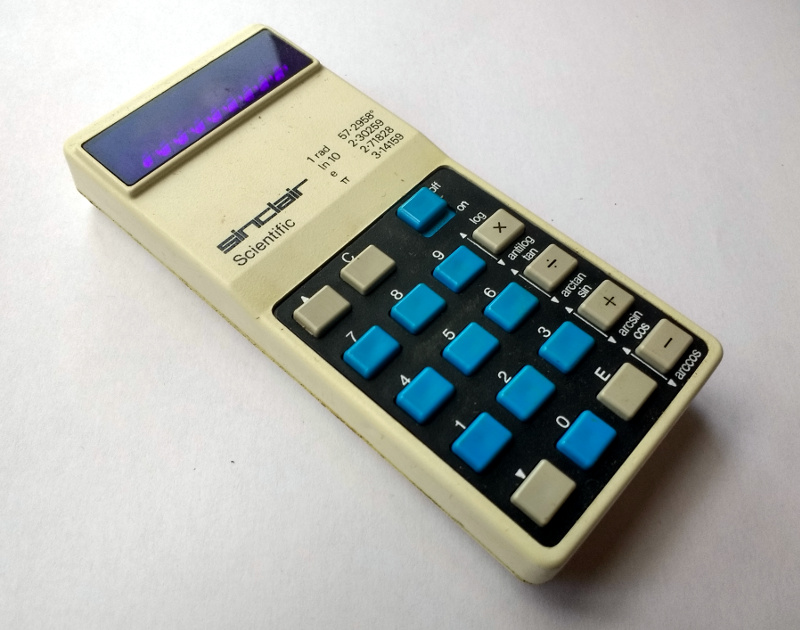
The Sinclair’s clean design still looks good four decades later.
Looking at it though as an adult, it becomes obvious that this is an interesting machine in its own right, and one that deserves a closer examination. What follows will not be the only teardown of a Sinclair Scientific on the web, after all nobody could match [Ken Shirriff]’s examination of the internals of its chip, but it should provide an insight into the calculator’s construction, and plenty of satisfying pictures for lovers of 1970s consumer electronics.
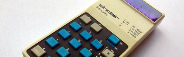
The Sinclair is protected by a rigid black plastic case, meaning that it has survived the decades well. On the inside of the case is a crib sheet for its RPN syntax and scientific functions, an invaluable aid when it comes to performing any calculations.
It shares the same external design as the earlier Sinclair Cambridge, a more humble arithmetic calculator, but where the Cambridge’s plastic is black, on the Scientific it is white. The LED display sits behind a purple-tinted window, and the blue-and-black keyboard occupies the lower two-thirds of the front panel. At 50 x 111 x 16 mm it is a true pocket calculator, with an elegance many of its contemporaries failed to achieve and which is certainly not matched by most recent calculators. Good industrial design does not age, and while the Sinclair’s design makes it visibly a product of the early 1970s space-age aesthetic it is nevertheless an attractive item in its own right.

 If you look at most stockists of electronic kits these days, you are likely to find an oscilloscope kit in their range. These are volume produced in China, and the same design trends appear across different models. You can buy surface mount or through-hole, and most of them feature a bare board with maybe a piece of laser-cut Perspex standing in for a case. There are one or two models appearing that come with a case though, and it was one of these that we ordered.