PTC Heaters For Reflow Soldering

Reflow soldering – setting components on a PCB in blobs of solder paste and heating the whole assembly at once to melt all joints simultaneously – has been the subject of many ingenious hacks. Once it was the sole preserve of industrial users with specialist microprocessor-controlled ovens, now there are a myriad Arduino-controlled toaster ovens, hot air blowers, and hotplates that allow hackers and makers to get in on the reflow act too.

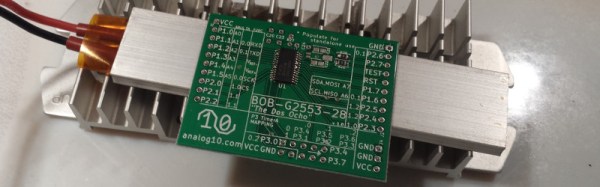
This morning a fresh idea in the reflow soldering arena has come our way. It’s not the most earth-shattering, but it does have some advantages so is worth a second look. [Analog Two] has successfully used a PTC heating element as a reflow soldering hotplate.

PTC heating elements are thermistors with a positive temperature coefficient. As their temperature rises, so does their electrical resistance. By careful selection of materials they can be manufactured with a sharp increase in resistance at a particular temperature. Thus when an electrical current is passed through them they heat up until they reach that temperature, then the current decreases as the resistance goes up, and they do not heat beyond that point. Thus as heaters they are intrinsically self-regulating. From our point of view they have another advantage, they are also cheap. Fitted as they are to thousands of domestic heating products they are readily available, indeed [Analog Two] found his on Amazon.

The heater chosen was a 200W 110V model with a temperature of 230 Celcius to match the solder he was using. They are also available for other mains voltages, and even at 12 and 24V for automotive applications. He reports that the time to reflow was about 90 seconds.

We’ve mentioned the advantages of this heater as its price and regulated temperature. Looking at the pictures though a disadvantage is its size. This is a reflow plate for small boards. There are larger PTC heater elements available though, it would be interesting to hear people’s experiences reflowing with them.

Hotplates for reflow soldering have featured before a few times here at Hackaday. We recently had this tiny plate, but we’ve also had a PID-controlled plate, and an Arduino-controlled domestic hotplate. We’re sure this is an avenue with further to go.
Using An FPGA To Generate Ambient Color From Video

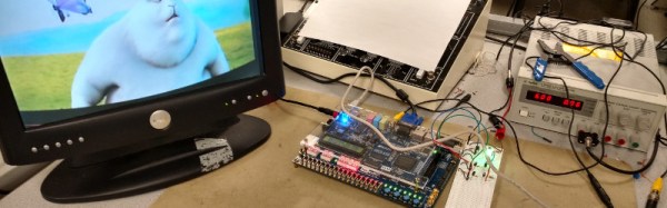
We should all be familiar with TV ambient lighting systems such as Philips’ Ambilight, a ring of LED lights around the periphery of a TV that extend the colors at the edge of the screen to the surrounding lighting. [Shiva Rajagopal] was inspired by his tutor to look at the mechanics of generating a more accurate color representation from video frames, and produced a project using an FPGA to perform the task in real-time. It’s not an Ambilight clone, instead it is intended to produce as accurate a color representation as possible to give the impression of a TV being on for security purposes in an otherwise empty house.

The concern was that simply averaging the pixel color values would deliver a color, but would not necessarily deliver the same color that a human eye would perceive. He goes into detail about the difference between RGB and HSL color spaces, and arrives at an equation that gives an importance rating to each pixel taking into account its saturation and thus how much the human eye perceives it. As a result, he can derive his final overall color by looking at these important pixels rather than the too-dark or too-saturated pixels whose color the user’s eye will not register.

The whole project was produced on an Altera DE2-115 FPGA development and education board, and makes use of its NTSC and VGA decoding example code. All his code is available for your perusal in his appendices, and he’s produced a demo video shown here below the break.

Continue reading “Using An FPGA To Generate Ambient Color From Video”

Hackaday’s Fun With International Mains Plugs And Sockets

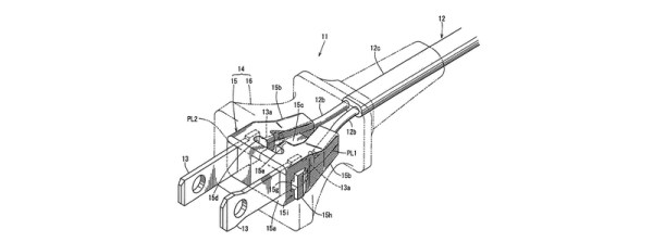
When we recently covered the topic of high voltage safety with respect to mains powered equipment, we attracted a huge number of your comments but left out a key piece of the puzzle. We take our mains plugs and sockets for granted as part of the everyday background of our lives, but have we ever considered them in detail? Their various features, and their astonishing and sometimes baffling diversity across the world.

When you announce that you are going to talk in detail about global mains connectors, it is difficult not to have an air of Sheldon Cooper’s Fun With Flags about you. But jokes and the lack of a co-starring Mayim Bialik aside, there is a tale to be told about their history and diversity, and there are also lessons to be taken on board about their safety. Continue reading “Hackaday’s Fun With International Mains Plugs And Sockets”

I2c Relay Expander Uses Nifty Card-Edge Connection

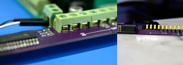
[Andrew Sowa] wanted to use an off-the-shelf relay board from Numato Labs. The board lacks a suitable computer interface, which meant that [Andrew] would have to build one, and its input connectors are screw terminals, which meant a lot of wiring. Undeterred, he created an i2c expansion board using an MCP23017 I/O port expander, and with a novel card-edge designed to mate with the screw terminals, solving both problems at once.
Continue reading “I2c Relay Expander Uses Nifty Card-Edge Connection”

Bricked Intel Tablet Lives Again

We’ve probably all taken a look at the rash of cheap Intel-Atom-based tablet computers and wondered whether therein lies an inexpensive route to a portable PC. Such limited hardware laden down with a full-fat Windows installation fails to shine, but maybe if we could get a higher-performance OS on there it could be a useful piece of kit.

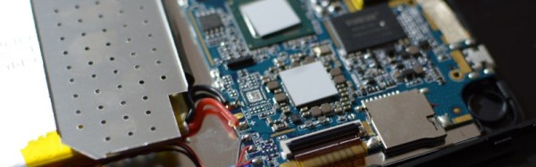
[donothingloop] has an Intel tablet, a TrekStore Wintron 7, bought for the princely sum of $60. Windows 10 didn’t excite him, so he decided to put Ubuntu on it, or more specifically to put Ubuntu on an SD card to try it on the Wintron before overwriting the Windows installation. His problem with that was a bug in the Baytrail Atom chipset which limits the speed of SD card access and made Ubuntu very slow, and in trying to fix the speed issue he managed to disable a setting in the BIOS which had the effect of bricking the machine. A show-stopper when the BIOS is in a tiny SPI Flash chip and can’t be wiped or restored.

What followed was an epic of desoldering the BIOS chip and reflashing it, though that description makes the process sound deceptively easy. The specification says it is a 1.8V device, so after attempts to flash it using an ESP8266 and then a home-made level-shifter failed, he was stumped. With nothing but a cheap tablet to lose, he tried the chip in a 3.3V programmer, and to his amazement despite the significant overvoltage, it survived. Resoldering the chip to the motherboard presented him with a working tablet that would live to fight another day.

We’d have said that this work might reside in the “Don’t try this at home” category, but since Hackaday readers are exactly the kind of people who do try this kind of thing at home it’s interesting and reassuring to see that it can be done, and to see how someone else did it. A tablet that can be bricked through a mere BIOS setting though is something a manufacturer should be ashamed of.

We like unbricking stories here at Hackaday, something about winning against the odds appeals to us. In the past we’ve covered Blu-ray drives crippled by dodgy DRM and routers rescued with a Raspberry Pi, but the crown has to be taken by the phone rescued with a resistor made using paperclips and pencil lead.

Working With Mains Voltage: The Electrifying Conclusion!

This is the second in a two-part series looking at safety when experimenting with mains-voltage electronic equipment, including the voltages you might find derived from a mains supply but not extending to multi-kilovolt EHT except in passing. In the first part we looked at the safety aspects of your bench, protecting yourself from the mains supply, ensuring your tools and instruments are adequate for the voltages in hand, and finally with your mental approach to a piece of high-voltage equipment.

The mental part is the hard part, because that involves knowing a lot about the inner life of the mains-voltage design. So in this second article on mains voltages, we’ll look into where the higher voltages live inside consumer electronics.

Continue reading “Working With Mains Voltage: The Electrifying Conclusion!”

Making A Fixed Voltage Power Supply Adjustable

Switch-mode power supplies are ubiquitous. Standard off-the-shelf modules in a consistent range of form factors available from multiple manufacturers. Globalized manufacturing and trade has turned them from expensive devices into commodity parts, and they long ago replaced iron-cored transformers as the go-to choice when a high-current low-voltage mains supply is required.

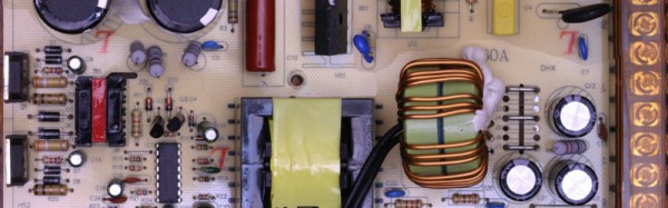
[Lindsay Wilson] faced a power supply problem for a motor he was working with, it required 7.4V and no off-the-shelf power supplies were to be found with that voltage. His solution was to take a 12V supply and modify it to deliver a variable voltage so he could dial in his requirement. A Chinese-made 12v 33A switch-mode supply was purchased, and he set to work.

In the event he was able to design a replacement feedback divider incorporating a rotary potentiometer, and achieve a voltage range of 5 to 15V. A small LED voltmeter mounted next to it in the PSU case gave him a very neat result.

Modifying a switch-mode supply to deliver a different voltage is a well-worn path we’ve covered at least once before. What makes Lindsay’s article worth a read is his reverse-engineering and examination in detail of the PSU circuit. If you’d like to learn more about all the different facets of design that go into a switch-mode PSU, it’s a detailed yet readable primer. We’d suggest reading our recent series on mains and high voltage safety before cracking open a switch-mode PSU yourself, but even if you’re never going to do it there’s something to be gained from knowing in detail how they work.

We’ve featured [Lindsay]’s work here at Hackaday a few times over the years. Check out his ultrasonic transducer power supply, which might be of use were you were building the ultrasonic soldering iron we featured not long ago, his laser stripping of ribbon cables, and his tale of decapping a USB isolator chip.