Dummy Load Uses Gray Code To Adjust Load In Small Steps

We’re not really interested in building a dummy load like this one for ourselves. But the concepts behind its design make for a nice little mental exercise as you read your way through the build description. [Pabr] wanted to build a dummy load which could be used to test a cheaply made gas generator. He wanted it to be as simple as possible, while providing a range of different loads. What he came up with is this monotonically adjustable load tester which uses gray codes for switching.

The video after the break does a good job of explaining the motivation for the design. Grey coding ensures that just one bit changes at a time. The example he uses to show the importance of this is when binary code transitions from 7 (0b0111) to 8 (0b1000). Three digits have been turned off and one has been turned on. Since he’s using light bulbs for his load this will turn off 700 Watts and then switch on 800W. That sudden jump in power draw can cause all kinds of problems with the generator’s engine. But the system he wired up will ensure that each flip of a switch moves in smaller steps.

Continue reading “Dummy Load Uses Gray Code To Adjust Load In Small Steps”

Exploiting DFU Mode To Snag A Copy Of Firmware Upgrades

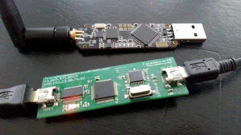
[Travis Goodspeed] continues his work at educating the masses on how to reverse engineer closed hardware devices. This time around he’s showing us how to exploit the Device Firmware Updates protocol in order to get your hands on firmware images. It’s a relatively easy technique that uses a man-in-the-middle attack to dump the firmware image directly to a terminal window. This way you can get down to the nitty-gritty of decompiling and hex editing as quickly as possible.

For this hack he used his Facedancer board. We first saw the hardware used to emulate a USB device, allowing the user to send USB commands via software. Now it’s being used to emulate your victim hardware’s DFU mode. This is done by supplying the vendorID and productID of the victim, then pushing the firmware update as supplied by the manufacturer. In most cases this shouldn’t even require you to have the victim hardware on hand.

Teens Pulled Over While Driving Their Wooden Roadster

From this view we would think the handmade wooden roadster (translated) was street legal. But it’s missing a few items that are required to take it out on the highway. The teenagers that built it were pulled over the other night (translated) and cited for driving without a speedometer or side indicator lights.

The image above shows the mark II of their design. Sadly they crashed the first version, which gave them a chance to overhaul the entire design. Now they have a proper frame which was welded from steel square tube. It’s got an impressive rack and pinion steering system and shock absorbing suspension in the front and rear. A dirt bike engine mounted behind the seats drives the rear wheels via a chain. They’ve used an Arduino to add turn signals, and have headlights for night driving.

[Gerrit] sent in the tip on this one and he figures that with an Arduino already being used in the vehicle it should be a quick fix to add a speedometer and get back on the road.

LED Wand Brings Ergonomics To Light Painting

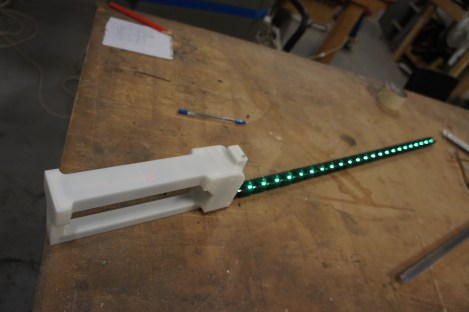
Quit struggling with hastily patched together electronics for your light painting images. Follow [Madox’s] example and build a light painting wand designed with your hand in mind.

You wield it much like a sword, but the only damage it does is to the long-exposure camera pointed its way. The RGB LED strip is controlled by the guts of a tiny little wireless router, a TP-Link TL-WR703N. This lets [Madox] connect using an Android device to upload different images. It also lets you tweak the settings like adjusting the timing between columns to match your exposure settings. The custom handle design provides a home and mounting plan for everything involved. It was 3D printed at the Sydney Hackerspace.

This isn’t the first light painting device running Linux. We’ve actually seen the Raspberry Pi used in much the same way but that final project involved using an entire recumbent tricycle to move the colored lights.

PIC Programming Adapter For The Raspberry Pi

Here’s another offering when it comes to PIC programming from the Raspberry Pi. The design seeks to adapt the GPIO header so that it may be used for programming PIC microcontrollers, but this does involve a bit more than just physically connecting pins to the target chip. Most of the PIC family require a 12V programming level, and this setup makes that possible.

The sets of NPN transistors shown in the schematic fragment above are arranged in darlington pairs. They’re actually switching voltage from the 6V linear regulator built into the system using the Pi’s 3.3V pins. There’s also a 12V regulator, so you’re going to need a power supply that is capable of sourcing more than that.

We’ve seen a similar concept before but this design carries it a step further. There are several status LEDs built into the programmer, and it includes support for detecting which chip is being programmed. So far this covers just four different chips, but we’re sure that it could be adapted to fit your own needs.

[via Reddit]

STM32 Driving A PCIe Video Card

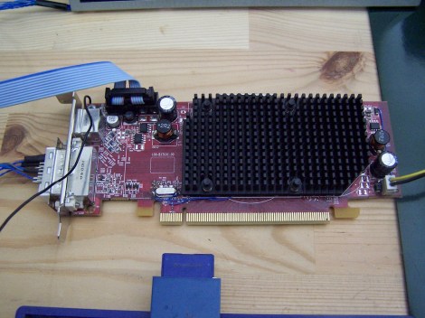
[Gpuhackr] chose his username to explain exactly how he spends his time. For instance, here he’s using an STM32 Discovery board to drive an AMD Radeon HD 2400 graphics card. The ARM microcontroller isn’t actually using the PCIe interface on the card. Instead, [Gpuhackr] has patched into the debugging interface built into the card itself. This isn’t quite as straight forward as it sounds, but if you do the wiring carefully it’s a pretty intersting way to connect an ARM to an LCD monitor.

This project would be almost impossible if it weren’t for the open source code which AMD has released. This lets him implement the card’s 3D rendering features. The demo directly programs the UVD Xtensa CPU which is on the video card. It draws a cube with color gradients on each side. The cube spins while the debug information is overlaid on the screen. In this case the ARM chip/board is really being used as a programmer to upload some custom firmware. But we think a real code-ninja could implement a communications protocol to open up a simple way to drive the card in real-time.

[Thanks uMinded]

USB To RS-232 Adapter Hacked To Use RS485 Instead

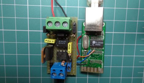
[André Sarmento] needed to connect a computer to an RS-485 bus. A simple converter can be sourced online, but the only thing he could find locally that was even close was a USB to RS-232 converter. He used that component to craft his own USB to RS-485 bridge.

RS-485 is often used for remote sensors as it provides a method of connecting electronics over long distances. The converter which he started with seems to be encased in a hot-glue-like substance. A bit of time with a torch and he was able to get to the components on the board. There are two stages, one which converts RS-232 to TTL, and the other converts TTL to USB. [André] removed the RS-232 chip and patched his own board (shown on the left) into its TTL lines. He was also able to add a few more configuration options, like using an external power source, and having a few jumper-selected resistor options.