Decoding RF Link Using A PC Soundcard

[Ray] wanted to use a microcontroller to send signals to some wireless power outlets. Instead of tapping into the buttons on the remote control he is using an RF board to mimic the signals. There are two hurdles to overcome with this method. The first is to make sure your RF module operates on the proper frequency. The second is to get your hands on the codes that are being sent from the remote control unit.

Now you could just hook your oscilloscope up to the transmitter and take a look at the timing of the signals. But most hobbyists don’t have that kind of high-end test equipment in their basement or garage shops. [Ray’s] approach uses something we all have available to us: a sound card and some open source software. He connected the data pin from his RF receiver to an audio plug and inserted it in the line-in jack of his computer. Using Audacity he recorded the signal as he pressed buttons on the transmitter.  This method not only captures the data, but the time stamps native to the audio editing program let him easily work out the timing for each signal.

It’s kind of amazing what you can do with this audio analyation technique. Earlier this year we saw it used to measure response time for DSLR cameras.

Continue reading “Decoding RF Link Using A PC Soundcard”

Lightsaber Lets You Pick Just About Any ‘blade’ Color

If you’re staging some epic Star Wars battles you could go original with Red or Blue lightsabers. But what if you decide you’re more of a fan of Jedi and want to go green? Or perhaps the prequels have inspired you to take on purple? Why choose at build time when you can adjust the color to match your mood.

[Phik] built himself a color-selectable lightsaber using RGB LEDs. He sourced a 5M strip of them from eBay for around $20. The pixels are not individually addressable, but each color channel can be driven with a pulse-width modulation signal to mix and match the final color. Now he could have gone with a microcontroller solution, but [Phik] decided to give himself a bit more of a challenge. He built three PWM circuits based on a 555 timer which can be adjusted with a potentiometer. It’s not going to kill any insects, but the keep-it-simple-stupid aspect of the project makes it something we could actually build ourselves. The same cannot be said for most of the replica builds we see.

Timer-based Cooling Helps Your Network Survive The Summer

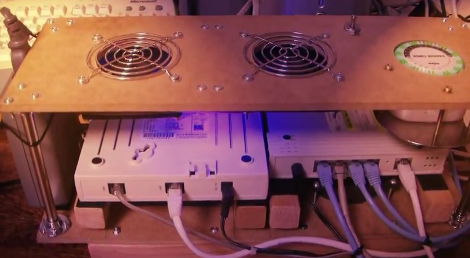
Start your week off with a smile thanks to the video [Sammy] put together. It shows off the cooling rack he made for his network equipment. The project was developed out of necessity as the summer weather was causing his modem and router to heat up and at some point one of them would just shutdown and refuse to work again for hours. We haven’t run into this ourselves but it’s good to know that over-temperature safeguards have been built into the equipment.

His solution was to build a rack that offers fan cooling above and below the two pieces of equipment. As with most of his projects, we think making the video (embedded after the break) was half the fun. In addition to playing around with a turntable for some extra special camera effects he gives us a good view of the overall build. The base includes spacers and velcro strips to hold the equipment in place above a pair of exhaust fans. The standoffs at each corner of the rack suspend a second pair of fans above the equipment. But it wouldn’t look nearly as good without some custom LED effects thrown into the mix.

This is purely timer-drive. It’s a plug-in module that uses mechanical timing to switch mains. But some creative circuitry (or a small microcontroller) could implement temperature-based switching instead.

Continue reading “Timer-based Cooling Helps Your Network Survive The Summer”

Junkyard Scavenging Nets A Tachometer To Play With

We never thought to hit the automotive junkyard to find electronics we could play with. But [Istimat] was able to pull this working tachometer from an otherwise destroyed motorcycle dashboard. The Kawasaki part has just three pins on the back of it. By connecting 12V to the IGN pin, ground to GND, and tapping a 12V wire on the unlabeled pin he was able to make the needle dance and knew he was getting somewhere.

His microcontroller of choice for the project is an Arduino board. But the 5V logic levels aren’t going to put out the square wave needed to drive the device. A search of the internet led him to a 2-transistor circuit which lets him get the results seen in the video. His plan is to add functionality that uses the Arduino to pull data in from just about any source and display it on the dial. That computer desk that featured all the CPU load readouts immediately comes to mind.

Do you think the square wave circuit is more complicated than necessary? Could this be done with just one NPN transistor and a pair of resistors?

Continue reading “Junkyard Scavenging Nets A Tachometer To Play With”

Printing Mounting Boards And Boxes For Hobby Projects

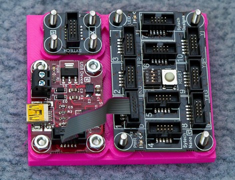
That’s a great base board for these Gadgeteer components. [Rob Miles] has been designing and printing mounting boards and enclosures for several of his projects. He just got into printing parts with the Ultimaker last week, and we’d say he’s found his stride. The board pictured here features nubs that act as stand-offs, and on the underside there are countersunk spaces for the bolt heads used as fasteners.

He started designing with Autodesk 123D but the interface didn’t really suit his working style. He switched over to FreeCAD and that experience fit him like a glove. He starts out with the sketch view to draw his parts, then extrudes that into the 3D model for further refinement before having the printer turn the digital into the real. This is the third board he produced in just one day of experimenting, but he is also showing off an enclosure he made for his thermal printer.

If you’re not working with boards that have nice mounting holes like these, don’t fret. We’ve seen 3d printed mounting systems that cradle the board, like these Raspberry Pi enclosures.

[Thanks Peter]

Raspberry Pi Controlled Tank Goes Deeper Than You Might Think

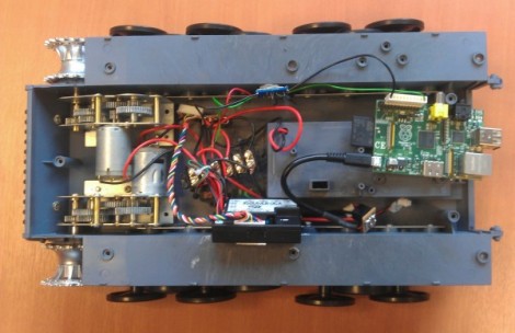
This remote control tank now takes its orders from a Raspberry Pi board. Well, actually it’s taking orders from commands pushed to the RPi board via SSH. The control scheme works out quite well. Using a low-profile WiFi dongle the RPi automatically connects to the wireless network when it is powered on. This makes it a snap to SSH into the device, and a more user-friendly controller will put a nice front-end into play at some time in the future.

But the real meat and potatoes of the hack comes in getting the RPi to talk to the tank’s circuitry. Just getting the Heng Long Tiger I remote control tank apart proved to be a ton of work as the treads need to be removed to do so and there’s a lot of screws holding it together. Instead of just replacing all of the control circuitry [Ian] wanted to patch into the original controller. To do so he spent a bit of time analyzing the signals with an oscilloscope and discovered that commands were coming in a Manchester encoded format. He established what various packets were doing, used a transistor to protect the GPIO pin on his board, and now has full control of the Tank. The final part of the hardware alteration was to power the RPi from the Tank’s battery.

After the break you can catch a demo of the reassembled tank sporting its new wireless controller.

Continue reading “Raspberry Pi Controlled Tank Goes Deeper Than You Might Think”

Computer Desk… Literally

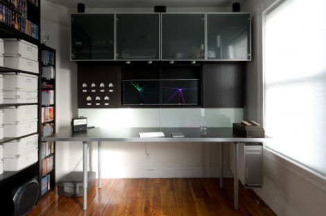
This piece of furniture begs the question, why think of a desk and a computer case as separate things? It combines Ikea furniture with electronic hardware to create the ultimate command center.

First the obvious parts: there’s a nook for the computer case that hangs just below the desktop off to the side, and the twin displays are mounted front and center. The divider between the cabinet pieces was cut away to allow the monitors to be wall-mounted. But things start to get interesting to the left of those monitors. You can see a series of dial displays in the door for that cabinet. Those meters were sourced from the MIT Flea Market and after a bit of alteration they display CPU load information fed to them by  an Arduino board. This also drives some LED strips which are mounted behind the frosted glass panel that we guess could be called a back splash. The heavier the load, the better the light show.

All of the power management is taken care of in the cabinet to the right of the monitors. The top row hides a printer, external hard drive backup system, and several gaming consoles. Heat will be an issue so exhaust fans were added to each of these partitions. They’re switched based on a temperature sensor in each. It’s a lot of work, but the outcome proves it was worth it.

[via Reddit]