Pimp My Scooter

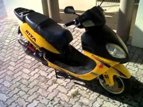
[Glen] built this shiny party machine out of a pretty sad-looking scooter. We’d bet you’re wondering why we think it’s a party machine when it looks so common? The only real giveaway in this photo is the custom exhaust, but hidden in the body of the beast is 720 Watts of party power plus a whole bunch of extras.

When he gets where he’s going, [Glen] parks his ride and lifts up the seat to unfold the entertainment. Attached to the underside of the saddle is a 720 Watt audio amplifier. It drives one big speaker under the seat, as well as two tweeters and two mid-range speakers that were fitted into the front console. But these days a party isn’t a party without some video, and that’s why you’ll also find a 7-inch LCD screen suspended from the upright seat. Tunes and videos are supplied by an iPod touch up front, or the PC he built into the ride. All it’s missing is a gaming console!

Continue reading “Pimp My Scooter”

Video Review: STM32F0-Discovery Board

The STM32 Discovery boards are nothing new, we’ve looked at them several times. But the newest sibling in the line might be just the thing to make the leap from your steadfast 8-bit projects. We got our hands on it and recorded a video review.

The STM32F0-Discovery gives you a programmer and ARM Cortex-M0 chip all on one convenient board. The top portion is the ST-Link V2 programmer, and includes jumpers and a programming header which let it easily program off-board chips.

The included microcontroller is an STM32F051R8T6 which includes 64kb of program memory and 8kb of RAM. Coming in at $1.80-3.77 in single units and in a hand-solderable LQFP package this raises an eyebrow for our future projects. It has an 8 MHz internal oscillator with 6x PLL which means you can run at 48 MHz without an external crystal (check out [Kenneth Finnegan’s] PLL primer if you don’t know what this is).

The only thing holding us back is the development environment. ST provides everything you need if you’re on Windows, but we want a Linux friendly solution. We know other Discovery boards have worked under Linux thanks to this project. This uses the same ST-LINK V2 so it should work as well. If you want one of your own head over the ST page to see if they’re still giving away samples. There should be a button labeled “Register for your FREE KIT”.

Morse Code Beacon Wins The LayerOne Badge Hacking Contest

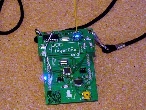
Ham skills prevail in this year’s LayerOne badge hacking contest. [Jason] was the winner with this Morse Code beacon hack.He got a head start on the competition after seeing our preview feature on the badge hardware development. It got him thinking and let him gather his tools ahead of arrival.

The hardware is segregated into two parts of the board. The lower portion is a take on the Arduino, and the upper portion is a wireless transmitter meant to control some cheap RC cars. [Jason] figured this was perfect for conversion as a CW beacon (continuous wave is what Morse Code is called if you’re a ham). The first issue he encountered was getting the badge to play nicely with the Arduino IDE. It was setup to run Slowduino firmware which uses the internal oscillator. [Jason] soldered on his own crystal and reflashed the firmware. He found that the transmitter couldn’t be directly keyed because of the shifting used in the RC car protocol. He cut the power to the transmitter, and found that it could be more accurately keyed by injecting power to one of the other pins. Check out the video after the break for a better explanation of his technique.

Continue reading “Morse Code Beacon Wins The LayerOne Badge Hacking Contest”

CalTech’s Manipulator-arm Equipped Robot

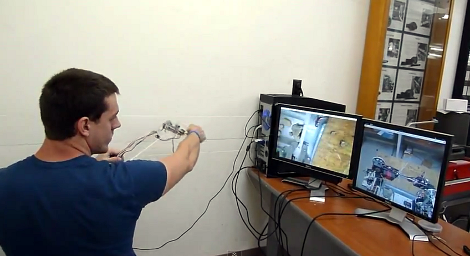
[Justin] wrote in to tell us about the rover which his CalTech team has entered in NASA’s Exploration Robo-Ops Competition. Their time to shine is later this week, but you can see some of the test footage after the break.

The operator pictured above is using a controller which is a scale model of the manipulator arm, with two cameras giving feedback. One of those monitors shows a feed from the arm itself, providing a view of the gripper. The other feed is a wide shot of the working area from the body of the robot. The arm has six degrees of freedom actuated by servo motors. The controller is a replica of the arm laser cut from acrylic. At each joint there’s a potentiometer whose value is used to establish the position of the frame.

At first we thought that this would be more fatiguing and less convenient than using a gaming controller. But as we look at the dexterity of the arm it becomes obvious that joysticks and buttons would just make things more difficult.

Continue reading “CalTech’s Manipulator-arm Equipped Robot”

How Anodization Is Used To Make Pretty IPod Colors

What do those colorful iPod Nano cases have in common with sapphires? In both substances the color is not on the surface, but integrated in the structure of the material. As usually, [Bill Hammack] unveils the interesting concepts behind coloring metal through anodization in his latest Engineer Guy episode.

We’re not strangers to the anodization process. In fact we’ve seen it used at home to change the color of titanium camping utensils. [Bill] explains what is actually going on with the electrochemical process; touching on facts we already knew; like that the voltage range will affect the color of the annodized surface. But he goes on to explain why these surfaces are different colors and then outlines how anodized metals can be dyed. That’s right, those iPod cases are colored with dye that will not wash or scratch off.

Pores are opened when the aluminum goes through anodization. Those pores are filled with dye, then the metal is boiled in water which closes them, sealing in the color. Pretty neat!

Continue reading “How Anodization Is Used To Make Pretty IPod Colors”

Using Spy-Bi-Wire With The MSP430 Launchpad

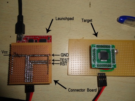
[Suraj] has been working with some larger MSP430 chips with won’t fit on the Launchpad board. But that’s okay because he built a shield and wrote a guide about using the Spy-Bi-Wire protocol for programming the chips.

SBW is a four-wire interface. In the past we’ve used all of the board’s programming connections for in circuit programming, but the chips that support SBW only need a connection to the SBW and TEST pins (of course the other two connections are for voltage and ground). This shield brings the four pins together into one male pin header. In the image above [Suraj] is using the technique to program an MSP430F4152. His guide is Windows-based, but looking back, [Sprite_TM] shows how to use SBW when debugging in Eclipse.

Failed Kayaking Data Logger Is Something We Want To See Succeed

How can your love of hobby electronics and your participation in the Canadian National Kayaking Team be combined? Why not use your technical know-how to provide a performance edge? [Geoff Clarke] decided to rig up a paddle for data capture to see if they could learn anything.

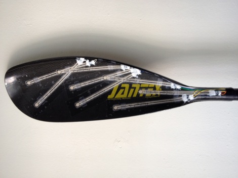
Here you can see that a series of flex sensors were applied to one of the business ends of the paddle. These are connected to a microcontroller which is constantly monitoring them and dumping the data onto an SD card. The design will provide about nine minutes of data before the storage is used up. That sounds like a number that might need improving. We could see this being useful to log a series of practice runs on the same course, but with different athletes. By graphing and comparing the data, you should be able to make observations about how the paddle is being held and when force is applied that could help the rest of the team improve.

But we’re way ahead of ourselves. The rig was given a premature test-run and the flex sensors were destroyed by the salt water. We wish this had worked out and hope that [Geoff] will give it another try after rethinking the water proofing.