Building A Battery-powered Motion Alarm

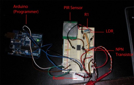
[Brad] was asked by his Sister to design a motion-based alarm that would help her catch her son sneaking out of the house at night. Obviously this didn’t need to be a long-term installation so he decided to throw something together that is only active at night and can be battery-powered. What he came up with is a light-sensitive motion sensor that uses very little power.

He knew that an Arduino would be overkill, and decided to try his hand at using the Arduino to develop code for an ATtiny85. It has an external interrupt pin connected to the output of the PIR module, which triggers action when motion is detected. The first thing it does is to check the photoresistor via the ADC. If light levels are low enough, the buzzer will be sounded. [Brad] measured the current consumption of his circuit and was not happy to find it draws about 2.5 mA at idle. He spent some time teaching himself about the sleep functions of the AVR chips and was able reduce that to about 500-600 uA when in sleep mode. Now all he has to do is find a nice place behind the house to mount the alarm and there’ll be no more sneaking around at night.

If you’re trying to keep a tight leash on your own kids you could always make them punch the time clock.

Sustainability Hack: Wind Turbine Battery Charger

Hit your parts bin and set aside an afternoon to build a wind turbine that recharges batteries. You can see two AA batteries hanging off the side of this small generator. You only need a few parts to make this happen, and chances are you have them sitting in your junk bin already.

The generator itself is a small stepper motor which can be pulled from a floppy disk drive or a scanner. The blade is cut from a single piece of 3.5″ (90mm) PVC pipe, with another piece of smaller-diameter pipe serving as the body of the turbine. The tail-fin makes sure it’s always pointing into the wind and was made from some plywood. As the blade spins, a current is induced on the control pins of the stepper motor. By building a pair of bridge rectifiers and using an RC filter you’ll get the most out of the generated current.

This turbine can charge a pair of NiCad batteries in about 10 hours, but it might be worth developing some smart circuitry to manage charging. If it were able to choose between a dedicated storage battery and the on-board battery holder you could put all of the wind energy to good use.

[Thanks Michael]

Bluetooth Communications For Android Devices Via Processing

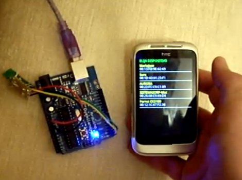
[Oscar] shows us how to use a Processing sketch for Android to communicate with Bluetooth devices (translated). It turns out this is easier than you might think. Processing and Android are both closely related to Java, and you can just import the Android libraries that deal with Bluetooth within the Processing sketch. That makes it easy to enable the Bluetooth modem when the sketch is launched, and manages connecting with devices as well as sending and receiving data.

For this example [Oscar] is using an Arduino with a Bluetooth module as a test device. His sketch first shows what devices are available, then connects to the one you select from the list. The 11 lines of Arduino code transmit a value via the serial port, and listens back for a command to toggle the LED on pin 13. [Oscar] takes time in his tutorial to show us how each step of the Processing sketch is assembled, instead of only posting the finished code.

[Thanks Sara]

Barebones PIC RFID Tag

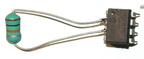
An inductor and 8-pin microcontroller are all that make up this barebones RFID tag. You might have done a double-take when first seeing the image above. After all, there’s nothing hooked up to the power and ground pins on the chip. As [Ramiro Pareja] explains in his post, the power is actually supplied via the I/O pins to which the inductor is soldered. It seems that each I/O pin has a parasite capacitor and a pair of clamping diodes inside the chip. When the AC current that is induced by the magnetic field of the RFID reader hits those pins, the capacitors charge and the clamping diodes form a bridge rectifier. This results in power being injected into the chip, which turns around and sends the RFID code back through the inductor.

This isn’t the first time that we’ve seen this concept. We featured a hack that is exactly the same except it used an AVR chip. This one uses a PIC 12F683 but should work with just about any 12F or 16F model. The code is written in Assembly and shouldn’t need any changes for different hardware. [Ramiro] does talk a bit about adding a decoupling capacitor to Vss and Vdd, as well as a tuning capacitor to the two I/O pins used above to help make the device a little more robust. But, as you can see in the video after the break, it works just fine without them.

Continue reading “Barebones PIC RFID Tag”

Over-the-air FM Radio Gains Internet Control

[Old bit collector] is giving up control of his radio dial to the Internet. He combined a couple of Parallax products which now allow him to tune, adjust volume, and toggle the power for an FM radio receiver.

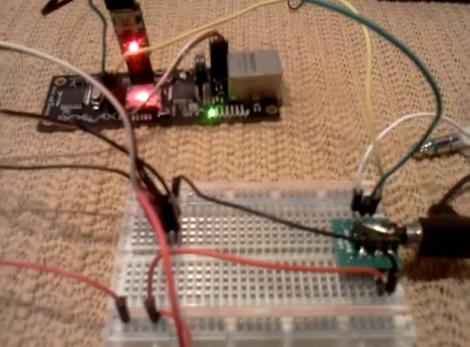
The setup is pretty simple. An FM receiver module is mounted in the breadboard seen above which helps to break out its control pins. Those are connected to a Parallax Spinnarette web server board. It’s auxiliary I/O pins are controlled via a web interface that he set up and plans to operate with the browser on his Android phone. But as you can see after the break, any web browser works as long as you know the correct address.

This is pretty good if you’re on a quest to make everything controllable from your smart phone. But we would love to use the concept to make our own streaming radio. You’d be able to tune in to all of your local stations from anywhere in the world.

Continue reading “Over-the-air FM Radio Gains Internet Control”

How To Decode IR Remote Control Signals With Your PICkit 2

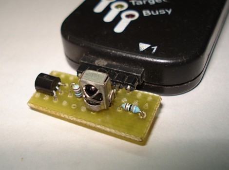
[SpiralBrain] needed to figure out the coding scheme used by an IR remote control so that he could use it with his own project. He built an IR receiver board for the PICkit 2 and figured out how to use some of the Microchip software to measure the timing of the incoming signal.

The hardware’s dead simple; a 38 kHz IR receiver does the heavy lifting by filtering out errant infrared light. When it does detect a signal with the correct frequency the output pin drives the base of a transistor to toggle the input pin on the PICkit 2. The breakout board has a pin header which makes it a snap to detach and store for later use. The PICkit 2 Logic Tool software captures this input, by setting the correct pin as a trigger and choosing a 10 kHz sample rate.

As we discussed in our PIC programming with Linux tutorial, the PICkit 2 really is far superior to its replacement, the PICkit 3. [SpiralBrain] mentions that it is more versatile than the newer version but doesn’t go so far as to tell us whether you can use this hardware with the PICkit 3 or not.

SNES Gamepad Coversion To USB

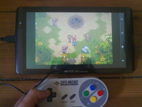
[Kekszumquadrat] wanted to use a classic controller to play emulator games on his Android tablet so he set out to convert an SNES gamepad to connect via USB. He found an old USB keyboard at a yard sale for about 3 Euros. He knew that the emulator he prefers has the option of remapping all the inputs to keyboard keys which means a USB keyboard has all of the electronics he would need to pull this off.

Once he had separated the keyboard circuitry from the case [Kekszumquadrat] plugged it into his Linux box and used Xev to establish how the keyboard matrix is set up. Xev is a common package that opens up an active window on the X desktop. When run from command line, any events that happen to the window will be echoed along with verbose data about that event. When it comes to keypresses, you’ll get the keycode you need. He simply shorted columns and rows until he found the desired mapping, then it was on to soldering.

The SNES controllers are very simple devices. As we’ve seen with previous projects, they use a serial-to-parallel shift register to gather button data and send it to the console. [Kekszumquadrat] simply soldered between button traces and keyboard matrix contacts. Once he finished, the keyboard parts were tucked inside of the controller case and he’s left with a USB controller that appears to be unaltered.