Road Apology/Gratitude Emitter Car LED Sign

Sometimes, when you’re driving, a simple wave when someone lets you in can go unnoticed and sometimes you make a mistake and a simple wave just isn’t enough. [Noapparentfunction] came up with a nice project to say ‘Thanks’ and ‘My Bad’ to his fellow drivers.

The display uses four Max 7219 LED matrix displays, so the total resolution is 32 by 8. [Noapparentfunction] came up with an inspired idea: using a glasses case to hold the LED matrices and Raspberry Pi. It’s easy to get into if necessary, stays closed, and provides a nice finished look. Having little knowledge of electronics and no programming skills, [Noapparentfunction] had to rely on cutting and pasting Python code as well as connecting a mess of wires together, but the end result works, and that’s what matters.
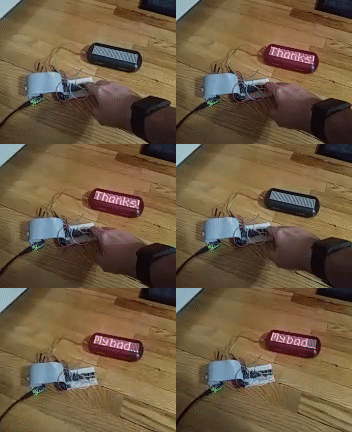
A network cable runs from the glasses case suction cupped to the rear window to another project box under the dashboard. There, the network cable is connected to two buttons and the power. No network information is passed, the cable is just a convenient collection of wires with which to send signals. Each of the buttons shows a different message on the display.

Depending on where you live, this might not be legal, and we’re sure many of our readers (as well as your author) could come up with some different messages to display. However, this is a cool idea and despite [Noapparentfunction]’s admitted limitations, is a nice looking finished product. Also, its name is Road Apology Gratitude Emitter. Here are some other car mod articles: This one adds some lighting to the foot well and glove compartment and this one on the heinousness of aftermarket car alarms.

60’s Comedy Rescued From Nigerian Basement

In the sixties, videotape used to film television programs was expensive. When a program had been shown as many times as the contract required the tape was wiped and reused, unless someone requested it be saved for some reason. At least, this was the BBC’s doctrine. Many episodes of the BBC’s programs have gone missing due to this reuse of the videotapes but sometimes the films of these episodes are found in an attic or storage facility. [Cplamb] brings us the story of the salvation of some episodes of British comedians Morecambe and Wise’ first series on the BBC, their first color series.

Do make duplicates, the BBC would film a television playing one of the videotapes. This film duplicate would be sent out to television stations around the world, rather than the tapes. The Morecambe and Wise film was found in the humid basement of a television station in Nigeria. Due to the conditions, the film was “diseased” and was in danger of decomposing into soup.

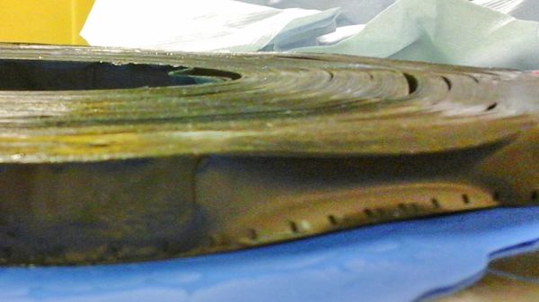
A series of hacks was used to restore the episodes from the rotting film stock. X-ray microtomography was used to scan a roll of film to see if this could be used. This worked because the film has a layer of silver oxide emulsion(the image) on one side and plastic (the film stock) on the other. A program was written so that the resulting voxels could be remapped into two dimensions in order to see the original frame. However, the volume that the machine could x-ray was small – using it on an item the size of a full roll of film would probably destroy the film, if it could be done. The next hack was to cut the film into small blocks using a laser cutter. This itself seems destructive but if you can either cut it up and scan it or let it turns into soup the choice is easy.

A second part of the story has been published, but the third article in the series hasn’t been yet, so we don’t know how the resulting film looks. But this is a pretty cool story involving scanning, x-rays, programming, and laser cutters — all hallmarks of the great hacks we see on Hackaday. Check out this article on the mechanics of film projection and this one on automatically scanning 8mm film for similar style hacks.

Seven-Segment Flip Clock Display Finally Finished

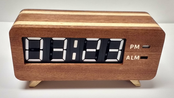
Earlier this year, we mentioned in a Hackaday Links article that [Spencer Hamblin] was in the process of building a seven-segment flip clock. Well, it’s finally finished, and it looks great!

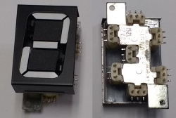
Vintage seven segment digits make up the display. These digits work the same way that flip-dot displays work – current through each segment’s coil creates a magnetic field which causes the segment to flip over. Current in the other direction creates the opposite magnetic field and flips the segment the other way. On these digits, there are three connections on the coils. The middle one is power and the other two are used to enable and disable the segment – ie., flip it one way or the other. To save on pins on the microcontroller, [Spencer] connected all the middle coil pins together on a digit. Each coil can be powered using a single pin on the microcontroller. Similarly, the segments for each digit are connected together as well, so one pin on the micro controls the same segment on each of the digits. The microcontroller in question is the AVR ATMega48.

There are two parts of the clock face left to do: AM/PM and whether the alarm is set or not. [Spencer] used a fifth digit, slightly offset, for those – the top and middle segments are used.

For the housing of the clock, [Spencer] used layers of offsetting colored wood. The wood (sapele and ash) were CNC cut and aligned. The back plate, also made from wood, holds buttons for setting the time and alarm, as well as some LEDs for what [Spencer] calls the “daylight alarm.” A capacitive sensor on the top of the unit (inside the wooden case) is used to turn the alarm off.

The result, after sanding and shellacing, looks amazing. [Spencer] nailed the art-deco look he was going for. There are plenty of pictures and the circuit designs, schematics and code are on [Spencer]’s Hackaday.io page, and you can find the Hackaday links post here. This is a complete log of a project we mentioned earlier on Hackaday, here, but there are other mechanical flip display clock projects, such as this DIY mechanical flip seven-segment prototype, or, you could create your own (really big) clock using this Lego mechanical seven-segment display.

via Reddit.

Finished Dryer Will Text You

Here’s a slightly different way to check on the status of your laundry. Instead of checking if the machine is vibrating, or listening for sound, or pulling everything apart and hacking an ESP8266 into it, check the power that the machine is drawing. This is what [Scrand] did in his IoT dryer build.

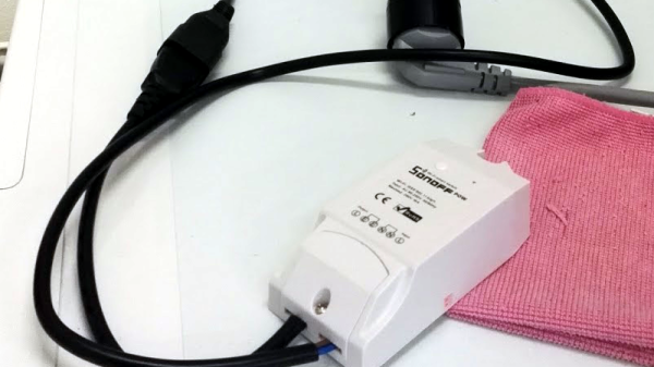
The secret behind the hack is the Sonoff POW, a small device that sits in between the wall and the dryer. It has a relay in it that controls it, but, importantly for this hack, it’s able to measure the power consumption used by what’s plugged into it. By installing the ESPurna firmware on it, he can now use all the power of the firmware to control and monitor what’s connected to the POW. He wrote a PowerShell script to monitor the http server now running on the POW checking on how much power is being drawn by the dryer. When that power drops, the laundry is done, and in the case of [Scrand], a text is sent saying so.

When you’re sitting on the couch relaxing, why get up every five minutes to check your laundry when you can have it text you when you know it’s done? Then you can decide whether to get up and deal with it or just leave it until later. The whole reason ESPurna exists to begin with is to check on the status of the laundry.  Or, you can go a bit overboard with this laundry room monitor.

DIY Wooden Building Blocks

If you have access to a drill press, saw, and sander, and are looking for a great present for smaller children this holiday season, [Jonny] may have you covered. He’s come up with a pretty good how to on making some simple block and dowel building blocks similar to the Tinkertoy building sets.

This is a fairly simple build if you have the shop tools, and if you only have hand tools available, is still quite doable. The blocks consist of square wooden blocks with holes drilled into them and a bunch of wooden dowels cut to size. [Jonny] adds a wooden box with a hinged lid for storing the blocks in as an added feature of the build,.

There are no LEDs lighting up, no Arduino-powered microcontroller involved, and they don’t connect to the internet, but that doesn’t make them any less of a great toy. Even without the shop tools, these could be made pretty quickly even by someone without prior experience with woodworking. If you’re interested in building block toys, check out this write-up about a way to combine different types of building blocks together, or check out this write-up about creating the frame of a DIY CNC mill with a metal building set.

Continue reading “DIY Wooden Building Blocks”

Trinket Chills Your Drinks

Who wants warm drinks? Well, coffee drinkers, we guess. Other than them, who wants warm drinks? Tea drinkers, sure. How about room temperature drinks? No one, that’s who. It’s silly to buy a refrigerator to cool down a single drink, so what option are you left with? Ice cubes? They’ll dilute your drink. Ice packs and a cooler? Sure, they’ll keep your drinks cold, but they’re hardly cool are they? No, if you want a cold drink the cool way, you build a thermoelectric cooler. And if you want to build one, you’re in luck, because [John Park] has a tutorial to do just that up on AdaFruit.

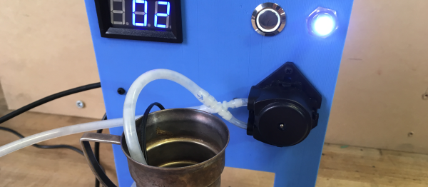
The parts list includes an AdaFruit Trinket M0, a more powerful version of AdaFruit’s Trinket line. The Trinket is used to control the main part in this build, a Peltier thermoelectric cooler, as well as the temperature display and switches. The other part controlled by the microcontroller is a peristaltic pump, which is used to do the dispensing of the liquid. The code to control everything is written in Python as the Trinket M0 comes with AdaFruit’s CircuitPython by default. Also included in the tutorial are the files for the stand, should you want to 3D print it or cut it with a CNC or laser cutter.

After the break, you can watch as [John] goes over the project and builds it, or go to the AdaFruit website and follow the instructions to build your own. As [John] says, there might be better ways to chill your drinks, but this is “definitely one of the more science-y and interesting ones.” For more projects using the Peltier Effect, try this one that uses the effect in sous-vide cooking, or this one, a Peltier cooled micro-fridge!

Continue reading “Trinket Chills Your Drinks”

ESP8266 As A Tape Drive

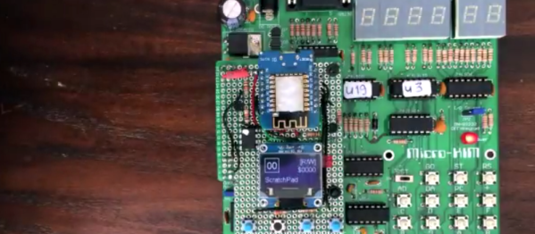
1976 was the year the Apple I was released, one of several computers based on the MOS 6502 chip. MOS itself released the KIM-1 (Keyboard Input Monitor) initially to demonstrate the power of the chip. The single board computer had two connectors on it, one of which could be used for a tape recorder for long-term storage. When [Willem Aandewiel] went to the Apple Museum Nederland in 2016, he saw one and felt nostalgic for his youth. He was able to get a replica, the microKIM, and build it but he wanted to use new technology to interface with this old technology, so he decided to use an ESP8266 as a solid state tape recorder.

One of the reasons the KIM-1 was so popular when it was released was that there was lots of documentation available. [Willem] used this documentation to figure out how the KIM-1 saves data to the recording device. An ATTiny85 is used to decode the pulse stream that the KIM-1 sends when saving because the timing was too tight to both “listen” and decode the bits as well as convert and store them. For loading programs, the data can be sent digitally as 1’s and 0’s to the KIM-1. This means that the ATTiny is only used for decoding and doesn’t have to re-encode the data.  Because of this, saving is slow, but loading is very quick.

To complete the project, [Willem] added four buttons, one each for rewind, record, play and fast-forward, and a screen so you can see which program is currently selected and can go from one program to another. As a nice throwback touch, record and play have to be pressed at the same time when saving. For more 6502 projects, check out this 6502 based DIY computer, or this 6502 built from discrete parts.

Continue reading “ESP8266 As A Tape Drive”