Model railroaders typically observe their project from high above. It would be neat to see what the world looks like to the residents of your little town, but getting down to their point of view is difficult, especially if you’re working in one of the smaller scales. For those working in the N scale, there’s now an easy way of observing your project as the train driver would see it: [Vassily98] managed to squeeze a wireless camera into an N-scale railcar.
The main challenge here was the extremely limited space available: the track in N-scale layouts is 9 mm wide, meaning that the whole system had to fit in just 23 x 20 mm2, the frontal area of a typical train car. One of the few cameras that fit within that profile was the RunCam Nano 4, which [Vassily98] connected to an ultra-tiny Team BlackSheep 5.8 GHz video transmitter.
While the basic concept of LEGO bricks might have changed little since the mid-20th century, some components such as motors and sensors are still affected by technological progress and end up obsolete and unsupported. [Roberts Retro] ran into this problem when he was building a festive train setup and realized he didn’t have the speed controller to match his train engine. Without that part, the engine would only run at full speed and derail as soon as it hit a curve. The official speed controller had been discontinued and was hard to find, so he had to build his own.
The basic components needed were an H-bridge driver to operate the motor and an ESP8266 to generate PWM signals. In order to keep the bricky appearance of the train engine intact, [Robert] hollowed out a few cheap imitation LEGO bricks to house the electronics. He also cut out slots for JST connectors, which are far more convenient to work with than LEGO’s brick-style connectors.
The ESP8266 runs ESPHome, which enables [Robert] to control the entire setup using Home Assistant. The train is programmed to run a few laps at the top of the hour and play choo-choo sounds from a mini MP3 player hidden in the coal car. That car also holds a standard AA battery holder to power the system, which makes it easy to swap the batteries without having to partially disassemble the train.
The Sinclair ZX Spectrum is fondly remembered by many for being their first introduction into the wonderful world of computing. Its advanced capabilities coupled with a spectacularly low price made it one of the great home computers of the 1980s, at least in the UK and nearby countries. What was less spectacular about the Spectrum was its awful keyboard: although a step up from the flat membrane keyboards of earlier Sinclair computers, the Spectrum’s tiny rubbery keys made typing anything more than a few characters a bit of a chore.
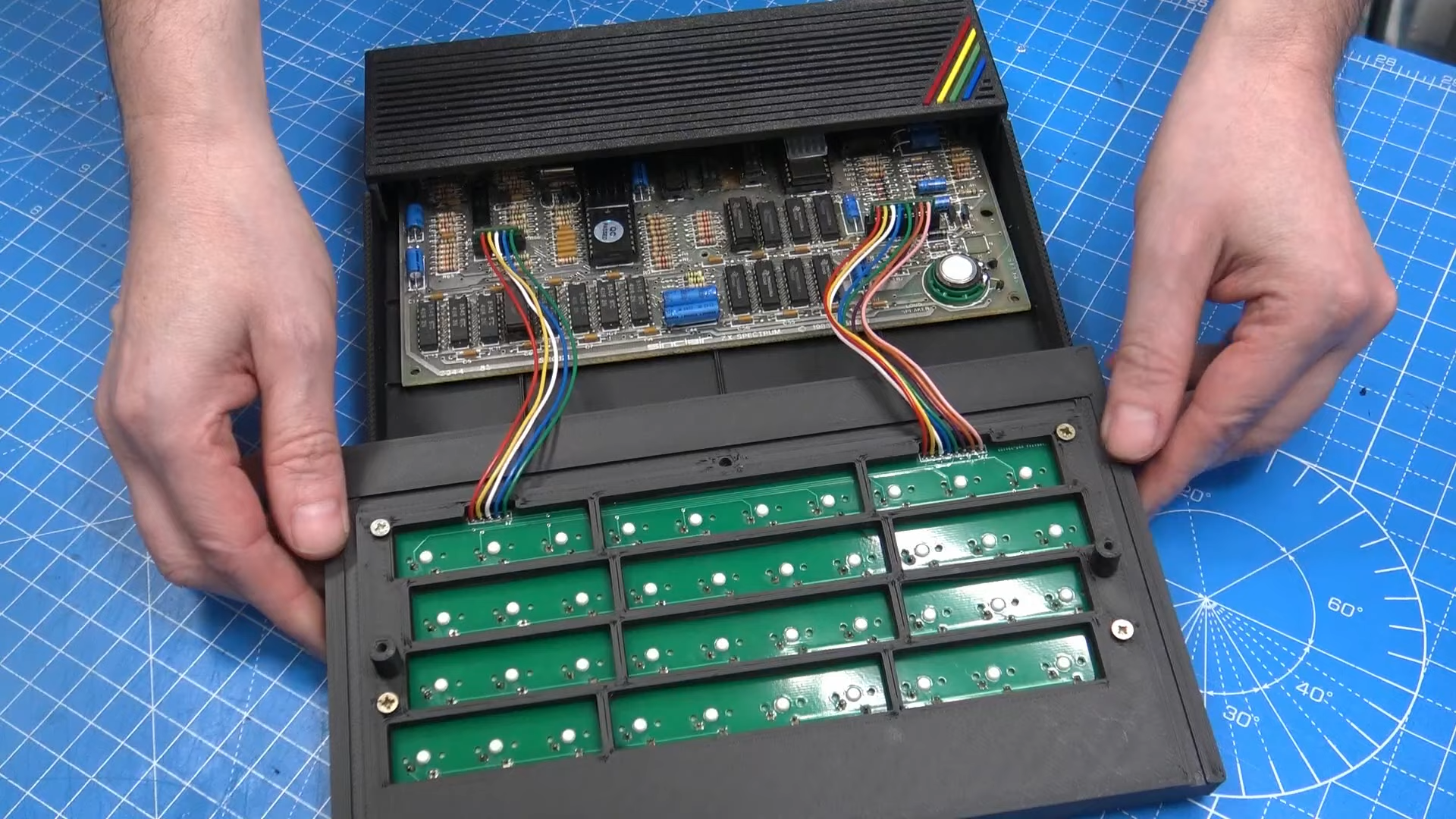
If you’re planning to do any serious programming on your Spectrum, you might therefore want to check out [Lee Smith]’s latest project in which he redesigns the Spectrum’s case to include a proper mechanical keyboard. [Lee] got this idea when he was looking for ways to fix a few Spectrums with broken or missing cases, and stumbled upon several projects that aim to recreate classic Sinclair machines using modern components. He took a keyboard PCB meant for the ZX Max 128 project, populated it with some high-quality switches, and added a modified set of keycaps from the ManuFerHi N-Go.
The new keyboard plugs into the original connectors and doesn’t require any board-level modifications.
Together, those parts formed a modern, comfortable keyboard that still had the proper labelling on all keys. This is rather essential on the Spectrum, since each key is also used to generate symbols and BASIC keywords: for instance, the “K” key also functions as LIST, +, LEN and SCREEN$.
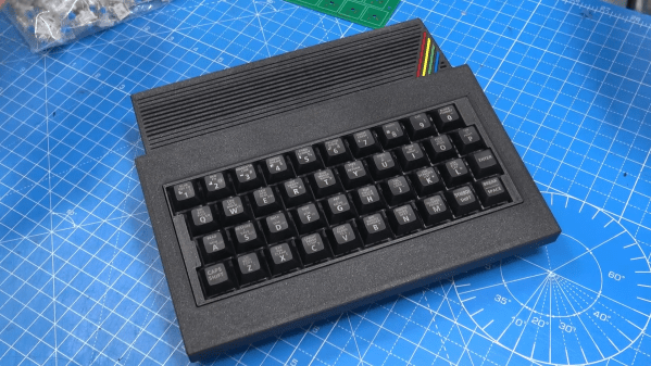
With the keyboard design settled, [Lee] set to work on the rest of the case: he designed and 3D-printed a sleek enclosure that takes the new keyboard as well as an original Spectrum mainboard. The resulting system is called the ZX Mechtrum, and looks fabulous with its matte black exterior and the obligatory four-coloured rainbow. A replaceable rear panel also allows several board-level modifications, like composite video or VGA output, to be neatly incorporated into the design.
Stabilizing an inverted pendulum is a classic problem in control theory, and if you’ve ever taken a control systems class you might remember seeing pages full of differential equations and bode diagrams just to describe its basic operation. Although this might make such a system seem terribly complicated, actually implementing all of that theory doesn’t have to be difficult at all, as [Limenitis Reducta] demonstrates in his latest project. All you need is a 3D printer, some basic electronic skills and knowledge of Python.
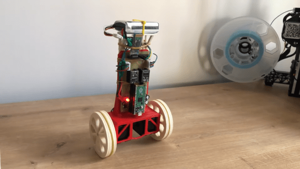
The components needed are a body, two wheels, motors to drive those wheels and some electronics. [Limenitis] demonstrates the design process in the video below (in Turkish, with English subtitles available) in which he draws the entire system in Fusion 360 and then proceeds to manufacture it. The body and wheels are 3D-printed, with rubber bands providing some traction to the wheels which would otherwise have difficulty on slippery surfaces.
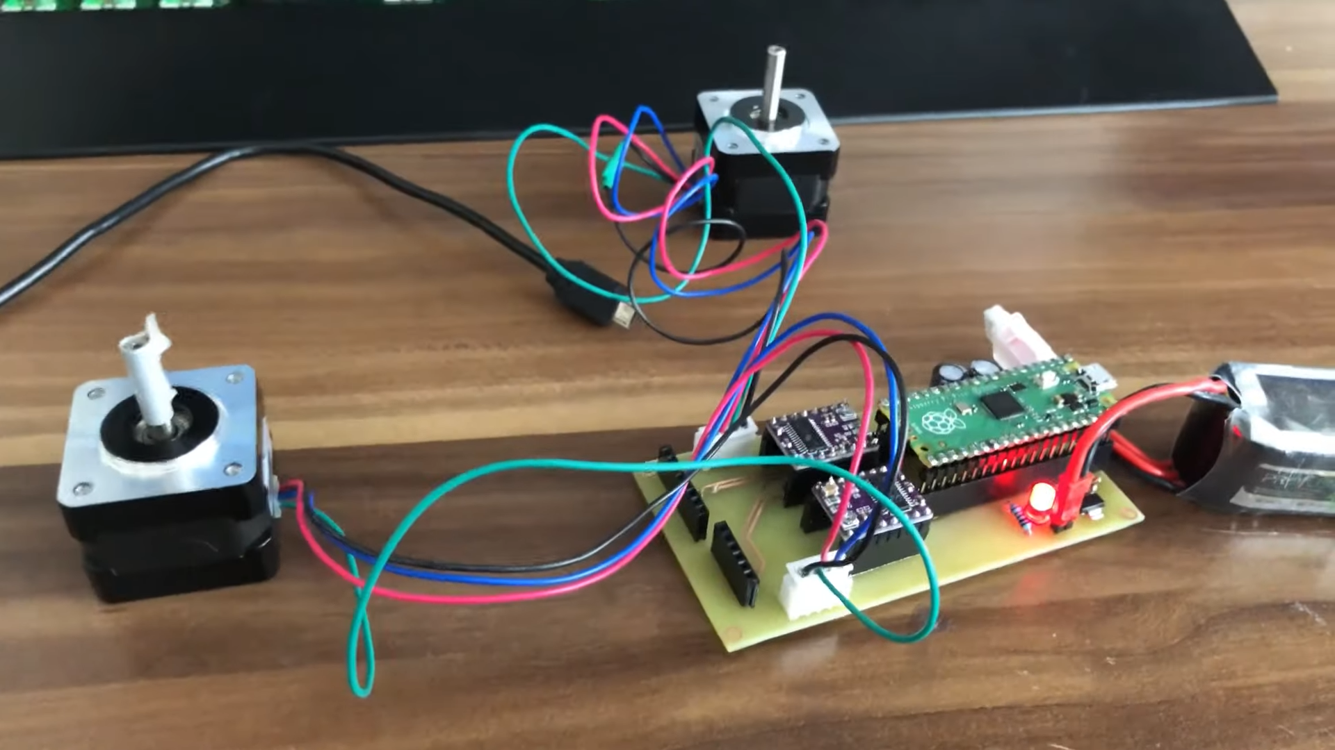
The PCB has just a few components, with most of the complexity handled by plug-in modules.
Two stepper motors drive the wheels, controlled by a DRV8825 motor driver, while an MPU-9250 accelerometer and gyroscope unit measures the angle and acceleration of the system. The loop is closed by a Raspberry Pi Pico that implements a PID controller: another control theory classic, in which the proportional, integral and derivative parameters are tuned to adapt the control loop to the physical system in question. External inputs can be provided through a Bluetooth connection, which makes it possible to control the robot from a PC or smartphone and guide it around your living room.
All design files and software are available on [Limenitis]’s GitHub page, and make for an excellent starting point if you want to put some of that control theory into practice. Self-balancing robots are a favourite among robotics hackers, so there’s no shortage of examples if you need some more inspiration before making your own: you can build them from off-the-shelf parts, from bits of wood, or even from a solderless breadboard.
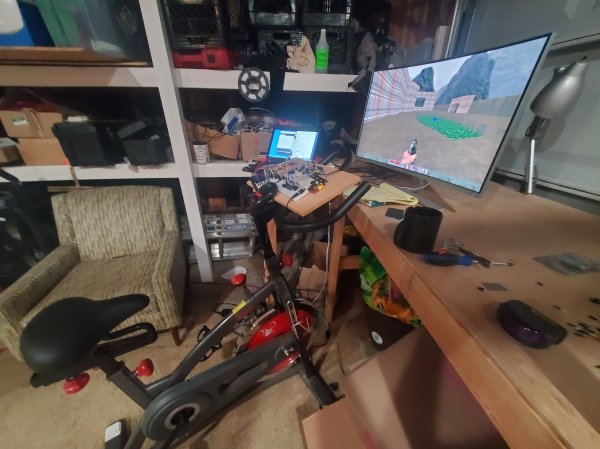
If you’re into cycling, there’s nothing better than heading out on the open road and feeling the wind in your hair. Unfortunately, climatic conditions make this uncomfortable or impossible at certain times of year, so you might be tempted to stay inside and play video games instead. Luckily, you can now get your gaming fix and still get in shape thanks to [Patrick]’s exercise bike game controller.
[Patrick] got himself a second-hand exercise bike and discovered that the speed sensor inside it was based on a magnet and reed relay, just like a regular bike computer. Reading out the sensor was therefore as simple as counting pulses using an Arduino Leonardo, and the USB HID protocol made it easy to turn the cycling mechanism into a one-dimensional game controller.
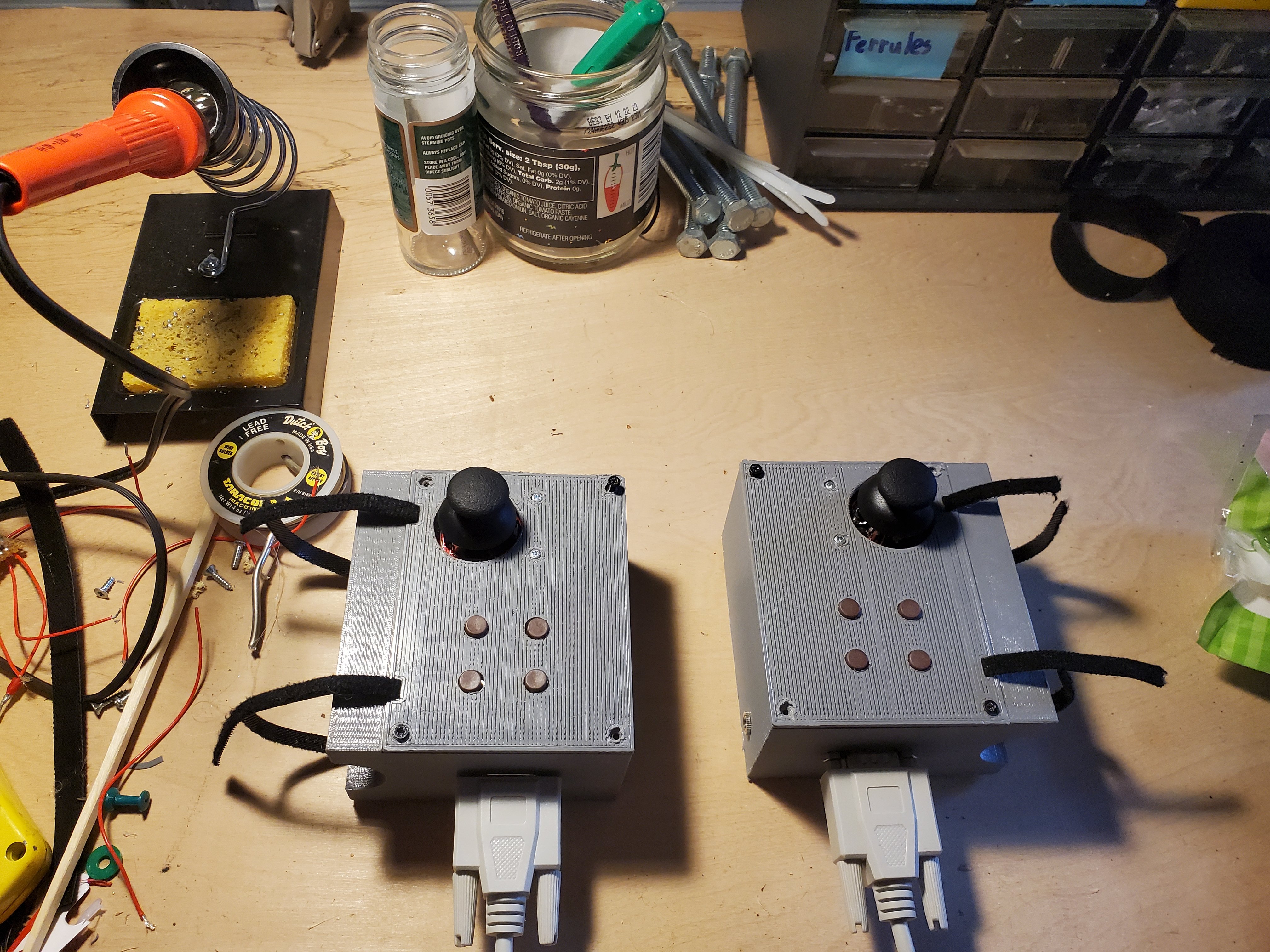
He then completed the setup by adding two 3D-printed handlebar-mounted gamepads with a few buttons and a thumbstick on each side. The total system now works as an ordinary gamepad, but with the option of using the bike as a forward/backward control.
We can imagine that this system will stay interesting for far longer than any off-the-shelf internet-connected exercise bike, because you can interface it with basically any game. [Patrick] demos his rig using first-person shooters like Doom and Team Fortress 2, but the possibilities are endless: how about turning FIFA games into bike polo? Or Mirror’s Edge into a bicycle courier adventure? After all, we’ve already seen how a similar game controller can turn Grand Theft Auto into something more like Grand Theft Bicycle.
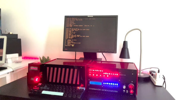
[Joshua Coleman] likes to design his own computers. Sometimes, that means drawing up bus architectures, memory maps and I/O port pinouts. Other times, he can focus his efforts more on the general aesthetics, as well as on building a great set of peripherals, as he shows in his latest ColemanZ80 project. Thanks to the RC2014 architecture defining most of the essential features of a classic Z80 computing platform, [Joshua] was able to design a modern retrocomputer that’s not only genuinely useful, but also looks as if it came off a production line yesterday.
The external design is a sight to behold: bright red laser-cut acrylic pieces form a neat, semi-transparent case with ventilation slots on the sides and lots of blinkenlights on the front. Inspired by 1970s classics like the Altair 8800, the front panel gives the user a direct view of the machine’s internal state and allows simple command inputs through a series of tumbler switches. The CPU, RAM and other basic devices are housed in one case, with all the expansion modules in a second one, linked to the mainboard through a 40-wire flatcable.
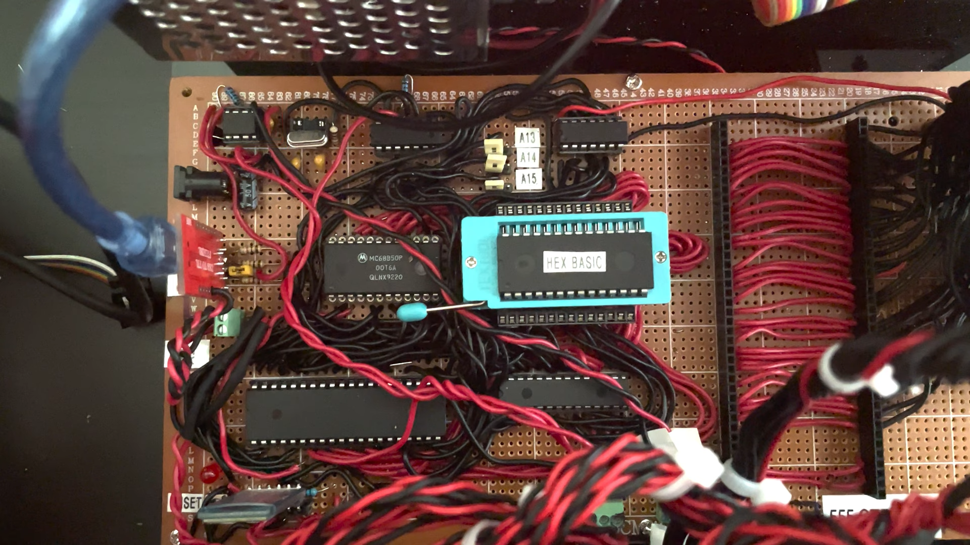
Lots of classic chips, but also loads of hand-routed wires grace the ColemanZ80’s mainboard.
Although the mainboard closely follows the RC2014 design, [Joshua] went through a lot of effort to tune the system to his specific needs. The expansion boards he built include an NS16550 UART to replace the default 68B50, a battery-backed real-time clock, a YM2149-based sound card and even a speech synthesizer module built around the classic SP0256 chip, of Speak & Spell fame. An even more unusual feature is the presence of an AM9511, one of the earliest math coprocessors ever made, to speed up floating-point calculations. All of these modules were built entirely by hand on prototype boards: we can barely imagine how much time this must have taken.
Output devices include a VGA adapter courtesy of a Raspberry Pi Pico as well as a regular 4-digit 7-segment LED display and a set of classic HP “bubble” LEDs. [Joshua] runs several demos in his video (embedded below), ranging from computing the Mandelbrot set to playing chiptunes on the YM2149. There’s plenty of scope for further expansion, too: [Joshua] plans to build more peripherals including a floppy drive interface and a module to operate a robotic car.
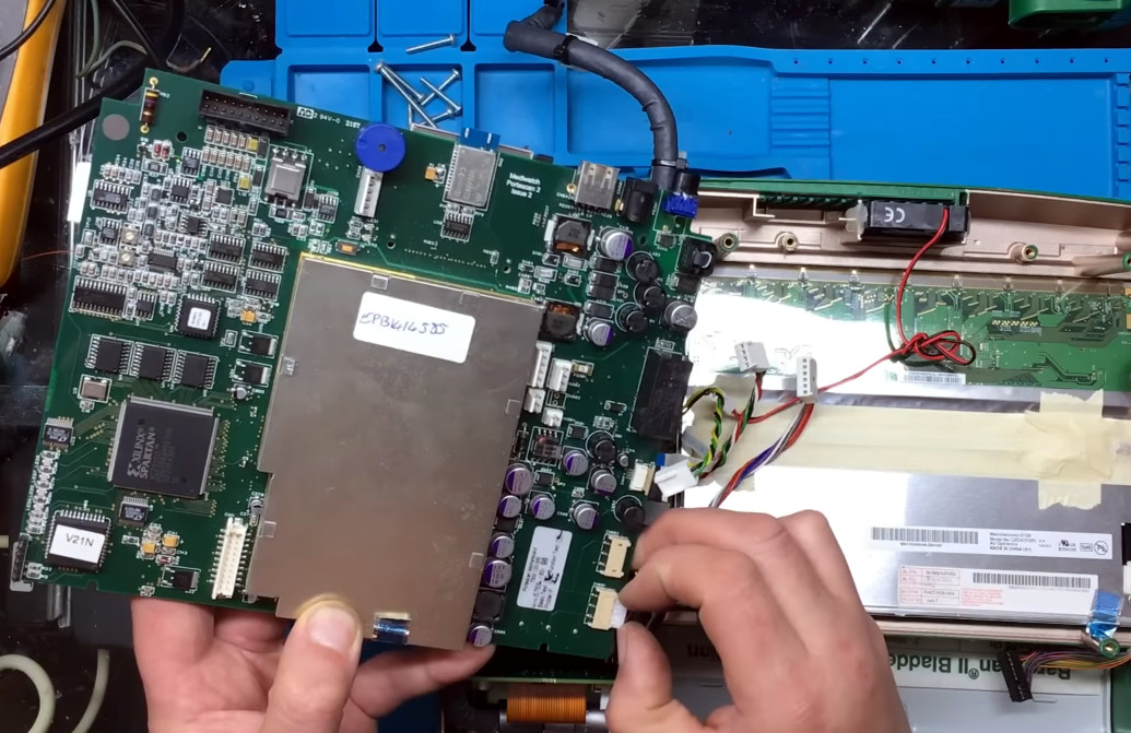
Medical equipment often makes for interesting teardown videos: the strict requirements imposed by certification bodies mean you’ll find good quality components and a high standard of design and manufacturing. But when [Buy It Fix It] bought an ultrasound scanner on eBay, he wasn’t interested in tearing it down: his plan was to use it to find out if his sheep are in lamb, so he went on to repair it and modify it for its new purpose.
The device in question is a Mediwatch Bardscan II, which is meant to be used for scanning people’s bladders. The mainboard has a completely different model number however, which suggests that the basic design is used for several types of ultrasound scanners. The system is powered by an AMD Geode processor that runs Windows XP Embedded stored on a CompactFlash card, so examining the internal software is easy: the scanner interface even runs on a regular Windows PC.
Several files on the internal drive point at hidden features, with filenames like kidney.dib and liver.dib indicating that the instrument can scan more than just bladders. The drive also holds several versions of the scanning app, as well as a .ini file in which lots of features can be enabled or disabled. By running the executable through x32dbg, [Buy It Fix It] was even able to recover the password to enable the “Advanced Settings” menu — it’s “u10” in case you were wondering.
With a bit of file editing, [Buy It Fix It] managed to turn the rather basic system into a way more flexible ultrasound scanner. For example, he can now adjust the scan depth, replay previous scans and make notes on top of any captured images. It can even run DOOM, as he demonstrates at the end of the video — though we can imagine his sheep might not enjoy the sight of their owner approaching them with a box full of flame-throwing demons.