Mini Apple IIe

The Mini Apple IIe That Runs On C.H.I.P.

[Cupcakus]’s mini Apple IIe must surely be a contender for the smallest computer running an Apple II emulator. We’d mentioned it a few months ago in a Links post when it had been posted to a forum along with a few videos of it in action, but now popular YouTube channel, [Tested], has released a video wherein they not only show what’s inside, and interview [Cupcakus] about his trials and tribulations in making it, but also go through the steps of making one of their own. Also, at the time of writing the Links post, [Cupcakus] hadn’t yet announced his detailed GitHub page about it.

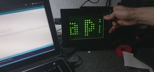
This mini Apple IIe runs on a C.H.I.P., a small $9 single board computer, and has a speaker and a TFT LCD display. Input is via a full-sized wireless keyboard. He doesn’t have joysticks working but that was an oversight and having realized how many games require joysticks, he has plans to add support for them. The case is 3D printed from models available on Thingiverse and links are on the GitHub page, along with all other details for making one yourself.

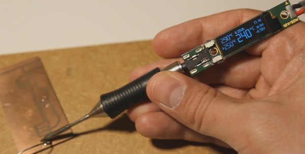
He did have to do some hacking. The video signal from the C.H.I.P. wasn’t available from the pin headers so he had to solder a wire directly to the board itself. The C.H.I.P. requires from 3.3 V to 5 V whereas the display wants 6 V to 12 V. To accommodate both he gets power from a 12 V drone battery and uses a 5 V buck converter for the C.H.I.P. And he had to modify the emulator to be legible on the low resolution of the display. The code for that is also available through the GitHub page.

While he uses the display as the screen for the Apple II emulator, it actually has two video inputs. So just in case he wants to show something on the display from another source, perhaps to watch a video, he’s made the second video input available using a socket in the back.

Want to see all the details for yourself? Check out [Tested]’s video below.

Continue reading “The Mini Apple IIe That Runs On C.H.I.P.”

From 50s Perceptrons To The Freaky Stuff We’re Doing Today

Things have gotten freaky. A few years ago, Google showed us that neural networks’ dreams are the stuff of nightmares, but more recently we’ve seen them used for giving game character movements that are indistinguishable from that of humans, for creating photorealistic images given only textual descriptions, for providing vision for self-driving cars, and for much more.

Being able to do all this well, and in some cases better than humans, is a recent development. Creating photorealistic images is only a few months old. So how did all this come about?

Continue reading “From 50s Perceptrons To The Freaky Stuff We’re Doing Today”

LED display controlled by Bluetooth speaker

How Many Hacks In An LED Display?

There are so many nice hacks in [Joekutz]’s retro LED display project that it’s hard to know where to start. There’s his DIY LED display controlled by an Arduino UNO. To have some text or picture for the display, he’s wired the output of a Bluetooth speaker directly to the Arduino, and sends it speaker tones that encode the text to draw. And as if that wasn’t enough, he’s hacked a quartz driver board from an analog clock to use the display as a clock as well.

Let’s start with the LED matrix display, perhaps the best excuse for trying your hand at shift registers. This display uses two such 8-bit shift registers daisy chained together feeding two 8-bit Darlington arrays. The display has ten rows of sixteen columns, and you guessed it, the columns are controlled by the sixteen shift registers. Two Arduino pins tell the shift registers which column to turn on. The rows are turned on and off using ten transistors controlled by ten more Arduino pins. Scanning at 80 frames per second he gets a nice, flickerless display.

To make both the LED matrix circuit board and the control board, [Joekutz] carved out isolation paths in copper clad boards using his homemade CNC mill. Be sure to check out the first video below to see his misadventures with it that ultimately led to his gorgeous boards.

Continue reading “How Many Hacks In An LED Display?”

Self balancing robot

Building A Self-Balancing Robot Made Easy

Not only has [Joop Brokking] built an easy to make balancing robot but he’s produced an excellent set of plans and software for anyone else who wants to make one too. Self-balancers are a milestone in your robot building life. They stand on two-wheels, using a PID control loop to actuate the two motors using data from some type of Inertial Measurement Unit (IMU). It sounds simple, but when starting from scratch there’s a lot of choices to be made and a lot of traps to fall into. [Joop’s] video explains the basic principles and covers the reasons he’s done things the way he has — all the advice you’d be looking for when building one of your own.

He chose steppers over cheaper DC motors because this delivers precision and avoids issues when the battery voltage drops. His software includes a program for getting a calibration value for the IMU. He also shows how to set the drive current for the stepper controllers. And he does all this clearly, and at a pace that’s neither too fast, nor too slow. His video is definitely worth checking out below.

Continue reading “Building A Self-Balancing Robot Made Easy”

Omnicopter catching a ball

A Flying, Fetching, Helping-Hand Omnicopter

Wouldn’t it be nice if you had a flying machine that could maneuver in any direction while rotating around any axis while maintaining both thrust and torque? Attach a robot arm and the machine could position itself anywhere and move objects around as needed. [Dario Brescianini] and [Raffaello D’Andrea] of the Institute for Dynamic Systems and Control at ETH Zurich, have come up with their Omnicopter that does just that using eight rotors in configurations that give it six degrees of freedom. Oh, and it plays fetch, as shown in the first video below.

Omnicopter propeller orientations

Each propeller is reversible to provide thrust in either direction. Also on the vehicle itself is a PX4FMU Pixhawk flight computer, eight motors and motor controllers, a four-cell 1800 mAh LiPo battery, and communication radios. Radio communication is necessary because the calculations for the position and outer attitude are done on a desktop computer, which then sends the desired force and angular rates to the vehicle. The desktop computer knows the vehicle’s position and orientation because they fly it in the Flying Machine Arena, a large room at ETH Zurich with an infrared motion-capture system.

The result is a bit eerie to watch as if gravity doesn’t apply to the Omnicopter. The flying machine can be just plain playful, as you can see in the first video below where it plays fetch by using an attached net to catch a ball. When returning the ball, it actually rotates the net to dump the ball into the thrower’s hand. But you can see that in the video.

Continue reading “A Flying, Fetching, Helping-Hand Omnicopter”

Music Reading For Machines

“Dammit Jim, I’m a hacker, not a musician!”, to paraphrase McCoy Scotty from the original Star Trek series. Well, some of us are also musicians, some, like me, are also hack-musicians, and some wouldn’t know a whole note from a treble clef. But every now and then the music you want is in the form of sheet music and you need to convert that to something your hack can play. If you’re lucky, you can find software that will read the sheet music for you and spit out a MIDI or WAV file. Or, as with my hand-cranked music player, you may have to read just enough of the music yourself to convert musical notes to frequencies for something like a 555 timer chip. We’ll dive into both cases here.

Continue reading “Music Reading For Machines”

Soldering pen with OLED display

Hackaday Prize Entry: OLED Displays For Soldering Iron Tips

Having soldered one end of a wire to a switch, you move on to the next step in your hack, soldering the other end of the wire to the more temperature sensitive pin 11 on the 6847 video chip. You set the soldering pen’s target temperature to something lower. You position the end of a tinned wire just so, with the solder held between the ring and pinky fingers of the same hand. You stare hard at the pin while you still know which one it is. Luckily this soldering pen has a display in the handle, close enough for you to glance at it quickly and see that the target temperature has been reached. You solder the wire in place.

The previous hack was one I did back in 1982 to my TRS-80 color computer but alas, there was no display in the soldering pen’s handle. I was just too early for the sweet soldering pen that [vlk] is making, and has entered into the 2017 Hackaday Prize.  It’s powered by a LiPo battery and can go from 25 to 400℃ in 5 seconds. The handle contains the electronics, including an STM32F031, and we’re impressed with how small he’s managed to get it all. Two buttons provide control and an OLED display simultaneously shows what looks like two target temperatures, the current temperature, voltages, battery charge level, and status. And if you want to make your own, his page even includes the schematics. Watch how easy it is to use in the videos below the break.

While [vlk]’s soldering pen has all the precision and ease of use you’d want, check out what is probably the simplest approach to soldering iron temperature control we’ve seen here. Or you could go for something in between, this one that’s also powered by LiPo batteries but has the display in a small laser cut box.

Continue reading “Hackaday Prize Entry: OLED Displays For Soldering Iron Tips”