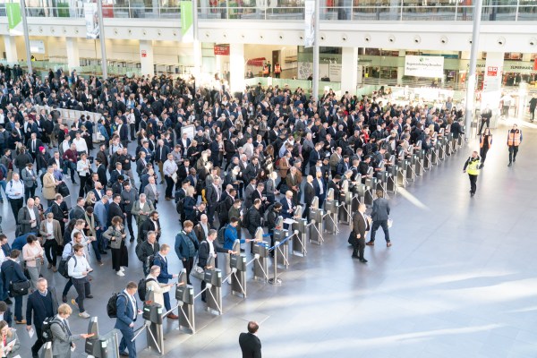
Last week, the world’s largest electronics trade fair took place in Munich, so I had to attend. Electronica is so big that it happens only once every two years and fills up 14 airplane hangars. As the fairly generic name suggests, it covers anything and everything having to do with electronics. From the producers of your favorite MLCC capacitors to the firms that deliver them to your doorstep, from suppliers of ASIC test equipment to the little shop that’ll custom wind toroids for you, that’s a pretty wide scope. Walking around, I saw tomorrow’s technology today from the big players, but I also picked up some ideas that would be useful for the home gamer.
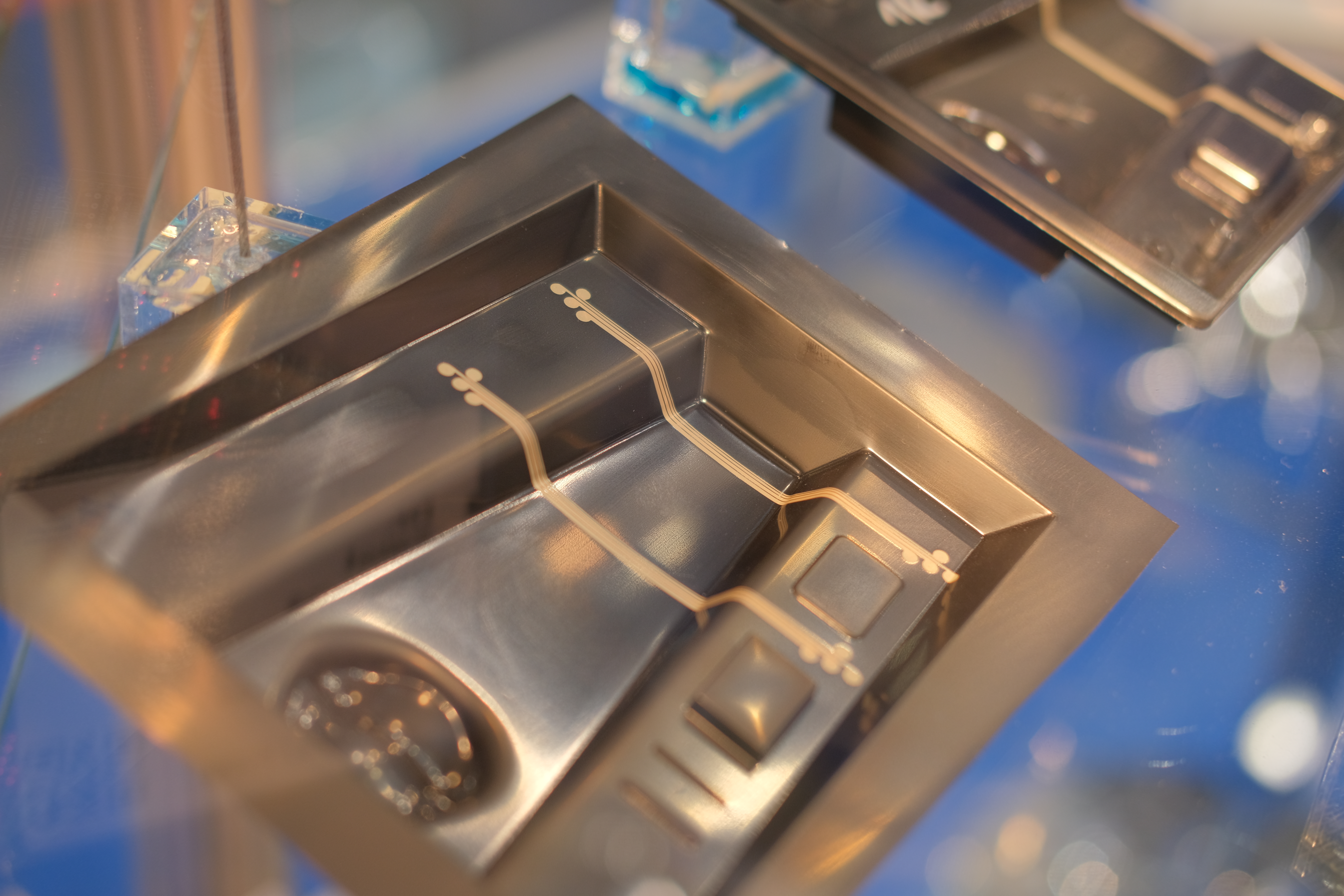
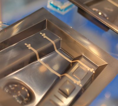 When I first walked in, for instance, I ran into the Elantas booth. They’re a company that makes flexible insulation and specialty industrial coatings. But what caught my eye was a thermoformed plastic sheet with circuit traces on it. To manufacture them, they cut out copper foil, glue it to a flat plastic sheet with a glue that has a little give, and then put it all together into a vacuum former. The result is a 3D circuit and organically formed substrate in one shot. Very cool, and none of the tech for doing that is outside of the reach of the determined hacker.
The Cool Stuff
All of the stands, big or small, try to lure you in with some gimmick. The big fish, firms with deep pockets, put up huge signs and open bars, and are staffed by no shortage of salespeople in suits. The little fish, on the other hand, have to resort to showing you the cool stuff that they do, and it’s more often the application engineers sitting there, ready to talk tech. You can guess which I found more interesting.
For instance when I walked up to an obviously DIY popcorn popper that was also showing 5000 FPS footage of kernels in mid-pop, I had to ask. The company in question was a small UK outfit that made custom programmable power supplies and digital acquisition gear that interfaced with it. You could plug in their box to some temperature probes, fire off the high-speed video camera, and control the heating and cooling profile without writing any code. Very sweet. Continue reading “A Hacker Walks Into A Trade Show: Electronica 2022” →