Hacking The Mi Band 10 Smart Band And Its Bestechnic SoC

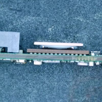
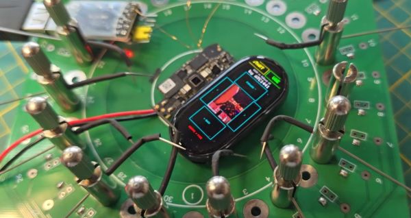
In between playing Doom on the most ergonomically challenged devices, [Aaron Christophel] likes to take a relaxing break with reverse-engineering Xiaomi Mi Band fitness trackers and writing custom firmware for them. Also so that he can play more Doom on those, natch. The latest subject comes in the form of the Mi Band 10, which features a BES2700iMP SoC, known internally at the manufacturer Bestechnic as the BEST1503. This is all documented on the GitHub project.

In the accompanying video we get some more details on this project, with the main challenge being that for this Mi Band 10 there’s no public SDK for its SoC. This was a major bummer until [Aaron] realized that the BEST1306 (BES2700IHC) is effectively the same SoC, but with a leaked SDK available via apparently audio-focused development kits. From there a BEST1503-compatible SDK could be assembled.

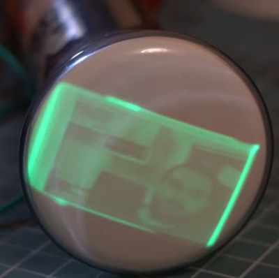
Naturally, to check that all of this was working correctly Doom was ported to the device courtesy of the GBADoom project. This mostly works aside from the display running in single-bit SPI mode instead of quad-SPI that it should be capable of, along with limited color depth. Despite burning all the tokens on the Claude, this provided little help, probably because the required information hasn’t leaked out of Bestechnic yet and ended up in the training data set.

Since the Mi Band 9 uses the same SoC, it’s expected that this reverse-engineered SDK will also work for that fitness band, though that hasn’t been tested yet.

Continue reading “Hacking The Mi Band 10 Smart Band And Its Bestechnic SoC”

Blender 5.2: Coming Soon With Improved Simulations

Blender is one of the poster children for Open Source Software– proof that something hacked together by enthusiasts could grow to rival the big boys in 3D modeling, animation and rendering after it was abandoned by its original corporate owners. Once you climb that initial learning curve, which can indeed feel cliff-like, you can do almost anything in Blender you can in paid competitors– almost.

Traditionally, one of the weak points has been simulations, with even those working in Blender professionally offloading simulation to programs like Houdini. According to [3Dan], once version 5.2 is out of beta in July, that may become a thing of the past. 

Simulations aren’t a necessary part of a 3D animation software, but they are very, very nice to have. If you want realistic-looking fluids, hair, or cloth, it’s incredibly difficult to animate it by hand. One, because there are so many degrees of freedom in, say, flapping cloth, keyframing is a major pain, but also figuring out how to make the model move and deform realistically is by no means trivial. It’s easier to offload all that on a physics simulation; then, as long as the physics is realistic, the animations will be as well.

That’s not easy, computationally speaking, and one thing that’s clear is there’s been work behind the scenes to optimize the simulation algorithms, not just improve the workflow, as the basic “drop cloth on a monkey head” demo now runs twice as fast. The new workflow itself bring simulations more into line with how Blender has been going– it’s part of geometry nodes now. So there’s simulation nodes you bring in, but that means things like tearing cloth become quite straightforward compared to the occasionally byzantine workarounds required before. This node-based workflow also brings Blender more into line with how paid software works these days.

[Dan] demonstrates the power of it by adding air pressure to a cloth simulation with some custom nodes, inflating and popping a fabric sphere. He also demonstrates how cloth simulation can be applied to animate realistic foliage. This update probably doesn’t have Houdini developer SideFX shaking in their boots, but it might allow some animators to stop paying that license and go fully-open source, which is great to hear.

While the work on the simulations engine is raising the bar on what was, traditionally, one of the weak points of the software, v5.2 brings oodles of improvements across the whole gamut of what blender can do– which is a lot. See them all on the official release notes. Even if you’re not into digital sculpting or animating, you may find yourself downloading a copy of Blender at some point to add texture to 3D prints, or make fancy resin-print miniature models FEM-friendly. The right addon can even let Blender do parametric CAD, if you want open-sorce and can’t stand FreeCAD. Though FreeCAD is getting better all the time, too.

Continue reading “Blender 5.2: Coming Soon With Improved Simulations”

How To Bias A CRT After Installation

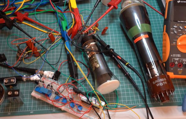
For most of us the abbreviation “CRT” brings to mind a monitor or TV. But at its core it’s about the special vacuum tube that makes the images appear.

Regardless of whether it’s just a simple monochrome CRT in an oscilloscope or a full RGB CRT, the basic steps to make it work in a device remain the same. In a recent video by [Void Electronics] these steps are worked through, including the biasing at the end that is necessary to get a stable image.

A big part of installing a CRT and driving it is knowing how to read its datasheet. Much like other vacuum tube types, there are heaters, control grids and a range of voltages to get right and keep happy. Even then you can still have a situation where you must troubleshoot problems, which is also touched upon in the video. All of this is demonstrated using an RFT B6S1 CRT as the subject, including how to build your own bias circuit.

Despite calling it an “obsolete skill”, there is still a lot of demand for CRTs in vintage lab equipment, arcade restorations and far more obscure fields that still have new CRTs produced for them. Not to mention that even today CRTs have characteristics that make them competitive with flat-screen technologies.

Continue reading “How To Bias A CRT After Installation”

Bernoulli Disk Goes “Wii!” When Plugged Into WiiU

The Bernoulli disk was a wild piece of 1980s hardware. Take a big floppy. Spin the platter at 1500 RPM just a micron or so from a read head. The airflow around that rapidly-spinning disk actually stabilizes the disk that close to the read-head via the Bernoulli effect, hence the name. Once upon a time, everybody wanted a Bernoulli Box to put under their Macintosh 512, but [Will It Work?] wanted to see how well these old drives held up to the 21st century… by using it to load games onto a WiiU. 

It’s not as crazy at is it seems. The WiiU is happy to read and write anything that looks like a USB mass storage device. The Bernoulli Box is of course pre-USB– even the later model 5 1/4″ drive [Will] is using from 1987. That means it uses SCSI, the USB of the 1980s. He’s got a 90 MB disk, though IOmega did make disks of higher capacity in that format, all the way up to 230 MB. Yes, the same iOmega of Zip-drive fame and infamy— but don’t worry, the peculiar pneumatic nature of the Bernoulli disks makes them immune to the click of death.

You might think it’s going to take a great deal of hacking and homebrew to get the WiiU talking to a SCSI drive from the 80s, but as we said in the introduction, Nintendo made this thing respect USB conventions, so all that’s needed is an SCSI-to-USB cable. Well, plus a passive SCSI 1 to SCSI 2 adapter to get the USB adapter to fit. Daisy-chaining adapters isn’t the most advanced hack, but the point isn’t how hard it was to pull off– it’s that we’re amazed it worked at all.

It doesn’t seem like the drive slows down the WiiU nearly as much as we’d expect, but then it’s not a console known for fast load times. The other suprizing detail is how much space the WiiU’s formatting sucked up, knocking the 90 MB disk down to only 68 MB– combine that with the WiiU’s firmware wanting to pad space for save files, and not much fits. Thus we don’t expect this odd tower of power to take off like the original did– still, if you had one of these back in the day, it might be a nice nostalgia hit to hear the drive whirring away.

If you think a disk drive is something Nintendo would never imagine for their consoles, think again! The Japanese version of the NES had the Famicon disk drive, which turns out to be essential if you want to run UNIX on that system.

Continue reading “Bernoulli Disk Goes “Wii!” When Plugged Into WiiU”

Autopsy Of A Freshly Cooked 10Gbit SFP+ Network Adapter

With the advent of affordable 2.5 Gbit, 5 Gbit, and 10 Gbit consumer networking gear, more and more people are taking advantage of these higher networking speeds, with [This Does Not Compute] having used 10 Gbit SFP+ modules over regular Cat-5e copper to connect to a NAS in the next room. Only problem was that after a while these SFP+ modules began to start dropping frames. On taking a closer look at these modules, he found that they were running pretty hot: 40°C while idle. A teardown of one of these modules showed severe discoloration due to heat.

Side view of the SFP+ module's PCB. (Credit: This Does Not Compute, YouTube)
Side view of the SFP+ module’s PCB. (Credit: This Does Not Compute, YouTube)

Inside these 10Gbit modules is the Marvell-branded Alaska X 88X3310/40P PHY, which despite the ‘low-power’ claims have a metal heatsink glued onto the actual IC and thermally coupled to the module’s metal enclosure. The other side of the PCB was quite discolored, further indicating how hot these modules run in operation. Some digging revealed that this can go up to around 2.5 watts.

Perhaps the most fascinating part of this teardown is the discovery of an 8051-based MCU that’s responsible for telling the switch the module is put into that it is a 30-meter multi-mode fiber module, presumably for compatibility purposes. It’s definitely an interesting feature of these FS-branded SFP+ modules.

These old modules were replaced with Wiitek-branded modules that are supposed to use only up to around 1.5 watts in operation courtesy of a newer chipset, in the hope that these wouldn’t fry themselves. At idle these do however still run at 30 °C. As noted in the comments, it might be a good idea to have active airflow over high-speed networking gear like this, as they generally can get pretty hot and sometimes crispy.

The final solution for the video’s networking problem was to just run single-mode fiber to the room and use appropriate SFP+ modules for that, also because these run noticeably cooler. If you still have room in your cable ducts, that would seem to be the optimal solution.

Continue reading “Autopsy Of A Freshly Cooked 10Gbit SFP+ Network Adapter”

Defeat Blood-Sucking Mosquitoes By Becoming The Bug Zapper

One of the stun gun modules with battery pack. (Credit: Dani Cruster DiWHY, YouTube)

Few things are more satisfying during a Summer night than hearing the crackle and pop of another mosquito hurling itself against a bug zapper and knowing that it won’t be trying to suck your blood any more. The only problem with those bug zappers, whether the mounted or hand-held type is that you cannot get every single attacking mosquito. Unless you were to put the bug zapper on yourself, of course. This is basically what [Dani Cruster] of the aptly named ‘DiWHY’ channel decided would be the right course of action.

The video is apparently dubbed over from the original Russian – with the team claimed to be based in Moldova – which probably explains a lot of the reasoning behind this engineering. At the core of the whole-body bug zapper is galvanized mesh, with a big question being how close you can get it to the body before said body gets zapped too. With about a millimeter of clearance between both layers of mesh required at 1 kV, this was another design consideration.

Ultimately the guts of stun guns were used, which output around 10 kV and thus require a 1 cm gap between the mesh layers. PVC plates were used to create the structural elements of the walking bug zapper suit, using a heatgun to form it into a body-appropriate shape. That’s when human testing started, to try and not make it zap the wearer.

The final suit of bug zapping armor uses six stun gun modules, each powered by a 3 V power source created from two 1.5 V alkaline cells that are good for an hour of zapping. One issue found during a human trial run was that the zip ties used turned out to actually cause arcing, which had to be addressed first before heading to the mosquito-infested woods. In the video these are said to be near Tarkov in what appears to be the national park in Russia’s Tver Oblast and clearly a prime mosquito breeding ground.

During the real-life test run many mosquitoes and apparently even some ticks find their electrifying demise, before for some reason they seem to clear out after an hour or so. Overall it seems to work well, even if it’s not that ergonomic and things get spicy when it starts to rain.

Continue reading “Defeat Blood-Sucking Mosquitoes By Becoming The Bug Zapper”

A drone is shown flying above some trees and a building. A pink cloud of dots appears above the drone, and a purple cloud below the drone. Grey crosshairs are to the right of the drone.

Seeing The World In Radio Waves With The QuadRF

Although the basic principle of radio direction finding is easy to understand (measure the phase difference between different antennas, then calculate the angle of arrival from this difference), the radio hardware to actually implement this has historically been hard for hackers to access. The QuadRF project aims to change this by building a phase-coherent four-channel SDR which makes direction mapping easy (GitHub repository).

The QuadRF uses two boards: one to receive and pre-process radio waves, and a Raspberry Pi 5 for additional processing. The RF board has four patch antennas, each capable of either transmitting or receiving in the 4.9 GHz to 6.0 GHz range, with switchable right- or left-hand polarization. For on-device processing, it uses a Lattice ECP5 FPGA, which uses two MIPI cables to connect to the camera and display interfaces on the Raspberry Pi. These form a very high-speed data exchange, and after further processing, the Pi can pass data on over Ethernet or Wi-Fi. Individual QuadRF boards can connect together in a lattice grid to form larger phased arrays.

The QuadRF’s software shows off its real strength: it’s compatible with standard programs like GNU Radio, but it also hosts a few of its own programs. The most striking of these is an “RF camera” which scans its entire frequency range at 30 fps, tracking the direction of detected signals and visualizing them on a spatial plot. When overlaid on a camera feed, this plot lets one easily see the radio signals emitted from electronics; as an example, the creators tracked a drone in flight, even distinguishing the two radio transmitters on the drone.

This isn’t the first multi-antenna SDR we’ve seen, though this is the first that could transmit. It’s important to be careful, though: some applications of this kind of hardware run afoul of arms regulations.

Thanks to [Swake] for the tip!