Reverse Engineering Quadcopter Protocols

Necessity is the mother of invention, but cheap crap from China is the mother of reverse engineering. [Michael] found a very, very cheap toy quadcopter in his local shop, and issued a challenge to himself. He would reverse engineer this quadcopter’s radio protocol. His four-post series of exploits covers finding the right frequency for the radio, figuring out the protocol, and building his own remote for this cheap toy.

[Michael] was already familiar with the capabilities of these cheap toys after reading a Hackaday post, and the 75-page, four language manual cleared a few things up for him. The ‘Quadro-Copter’ operated on 2.4GHz, but did not give any further information. [Michael] didn’t know what channel the toy was receiving on, what data rate, or what the header for the transmission was. SDR would be a good tool for figuring this out, but thanks to Travis Goodspeed, there’s a really neat trick that will put a 2.4GHz nRF24L01+ radio into promiscuous mode, allowing [Michael] to read the transmissions between the transmitter and quadcopter. This code is available on [Michael]’s github.

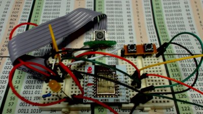
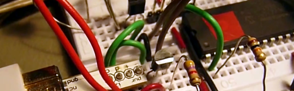
A needle in an electromagnetic haystack was found and [Michael] could listen in on the quadcopter commands. The next step was interpreting the ones and zeros, and with the help of a small breakout board and soldering directly to the SPI bus on the transmitter, [Michael] was able to do just that. By going through the nRF24 documentation, he was able to suss out the pairing protocol and read the stream of bytes that commanded the quadcopter.

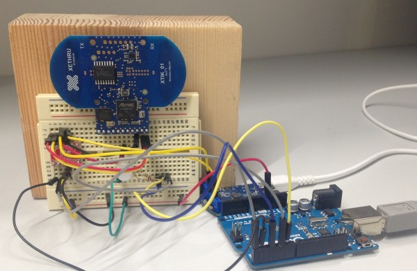
What [Michael] was left with is a series of eight bytes sent in a continuous stream from the transmitter to the toy. These bytes contained the throttle, yaw, pitch, roll, and a ‘flip’ settings, along with three bytes of ‘counters’ that didn’t seem to do anything.  With that info in hand, [Michael] took an Arduino Nano, an nRF04L01+ transceiver, and a Wii nunchuck to build his own transmitter. If you’re looking for a ‘how to reverse engineer’ guide, it generally doesn’t get better than this.

You can check out a video of [Michael] flying his Wiimoted quadcopter below.

Continue reading “Reverse Engineering Quadcopter Protocols”

Hacklet 97 – Camera Projects

We last covered camera projects way back in Hacklet #11. A ton of camera projects have been added to Hackaday.io since then. While the rest of the world is taking selfies, hackers, makers, and engineers have been coming up with new ways to hack their image capture devices. This week on the Hacklet, we’re taking a look at some of the best camera projects on Hackaday.io!

pixelzFirst up is [aleksey.grishchenko] with PiXel camera. PiXel is a camera and a live video display all in one, We wouldn’t exactly call it high-definition though! A Raspberry Pi uses its camera module to capture images of the world. [Aleksey] then processes those images and displays them on a 32 x 32 RGB LED matrix. This matrix is the same kind of tile used in large outdoor LED signs. The result is a surreal low resolution view of the world. Since the Pi, batteries, and camera all hide behind the LED matrix, there is an unobstructed view of the world around you. [Aleksey] used  [Henner Zeller’s] matrix library to make this hack happen.

imagerNext up is [Esben Rossel] with Linear CCD module. [Esben] is building a Raman spectrometer, much like 2014 Hackaday Prize finalist [fl@C@] with his own ramanPi. The heart of a spectrometer is the linear image capture device. Both of these projects use the same TCD1304 linear CCD. Linear Charge Coupled Devices (CCDs) are the same type of device used in flatbed document scanners. The output of the CCD is analog, so an ADC must be used to capture the data. [Esben] is using an STM32F401RE on a Nucleo board as the control logic. The ST’s internal ADC converts the analog signal to digital. From there, it’s time to process all the spectra.

wiimote-cam[Chiprobot] brings the classic Wii remote camera to the internet of things with
ESP8266 meets Wii Mote Camera. The Wii remote uses a camera which doesn’t output images, instead it plots the location of up to four IR LEDs. Normally these LEDs are located in the poorly named sensor bar that is sold with the Wii. Hackers have been using these cameras in projects for years now. [Chiprobot] paired his camera with the modern classic ESP8266 WiFi module. The ‘8266 is programmed to read data from the camera’s I2C bus. It then sends the data as an SVG request to the W3C website. W3C returns a formatted image based on those coordinates. The resulting image is a picture of the IR LEDs seen by the camera. Kind of like sending your negatives out to be developed.

photoboothFinally, we have [GuyisIT] with Raspberry Pi Photobooth. Photo booths are all the rage these days. First it was weddings, but now it seems like every kids party has one. [GuyisIT] didn’t rent a booth for his daughter’s birthday, he built one using his Raspberry Pi and Pi camera. The project is written in python, based upon [John Croucher’s] code. When the kids press a button, the Pi Snaps a series of pictures. The tiny Linux computer then joins and rotates the images while adding in some superhero themed graphics. Finally the Pi prints the image on to a photo printer. The biggest problem with this hack is re-triggering. The kids loved it so much, they kept pressing the big red button!

If you want to see more camera projects, check out our updated camera projects list! If I missed your project, don’t be shy! Just drop me a message on Hackaday.io. That’s it for this week’s Hacklet. As always, see you next week. Same hack time, same hack channel, bringing you the best of Hackaday.io!

An Introduction To Series Elastic Actuators For A Robot

Perhaps one of the most interesting YouTube channels to follow right now is [James Bruton’s] channel for XRobots.co.uk — he’s a prop maker, a toy maker — and as his site implies, a robotics guru. Put them altogether and watch him make some of your childhood dream projects come true. He’s currently working on a real-life robot creation of Ultron, and he’s messing around with Series Elastic Actuators right now.

In an earlier part of the project, he built a small robotic arm to demonstrate the motion capture suit he’s going to use to control Ultron (if all goes according to plan he’ll have a walking robot following his every move!). He showed how the basic RC servo motor driven arm works, and how it probably wouldn’t be the best to scale up since it has no external feedback — if he has a full size Ultron robot swinging its arms around, someone could get hurt.

Which led him to designing his own prototype Series Elastic Actuators using an Arduino, potentiometers, some elastics, and a geared DC motor.

Continue reading “An Introduction To Series Elastic Actuators For A Robot”

Hacklet 74 – Well Balanced Projects

Balance: we humans take it for granted. Without the sense of balance provided by our inner ears, we would have a hard time standing or walking around. What’s easy for us can be very hard for machines though. Projects that balance things have long been a challenge for engineers, makers and hackers. And rightly so, as building a machine to keep an object in balance often requires some novel electronic and mechanical solutions. This week’s Hacklet is all about projects that keep an object – or themselves – in balance.

wheelWe start with [Manuel Kasten] and Balance Wheel. Inspired by a project at Chaos Communication Congress, [Manuel] created a hack that looks timeless. A stainless steel ball is balanced on top of a wooden wheel. The system detects the ball’s position using a solar cell. More light on the cell means the ball is slipping off the wheel. The system counteracts this by spinning the wheel to oppose the falling ball. In the old days this would have been an analog system. [Manuel] made things a bit more modern by using an ATmega644p processor. The video shows the wheel spinning a bit fast, as the system was tuned for a ping pong ball rather than a heavy steel roller.

sidewayNext up is [Jason Dorie] with Sideway. Sideway is a two-wheeled skateboard that self-balances. One of the best parts of this project is that most of the mechanical components are from electric scooters, which means they are easy to source. The frame is even easier: A solid piece of plywood supports the rider and all the electronics. Two scooter motors are driven by a Sabertooth 2x32A motor controller. A Parallax Propeller performs the balancing act, obtaining IMU data from an ITG3200 digital gyro and an ADXL345 accelerometer. Speed is controlled by leaning forward and back, like a Segway. Steering is controlled by a Wiimote nunchuck. Sideway is powered by 3 cell LiPo batteries. [Jason] says this ride gets a lot of attention every time he takes it out.


balance-robot[Dominic Robillard] developed his Stair-climbing self-balancing robot as part of his masters degree at the University of Ottawa. We don’t know what grade his advisors gave him, but we give this project an A+. The robot is a 4WD off-road monster. Two heavy-duty drive motors give it tank style steering. The most impressive part of the robot are the two arms which allow it to roll its entire chassis up and over obstacles which would stop much larger robots. [Dominic’s] robot isn’t just statically balanced though – it can rear up and ride on two wheels Segway style. If it does tip over, the arms will lift it right back up!


terrabalanceFinally, we have [Paul Bristow] with Terabalance. [Paul] got his hands on an early copy of the TeraRanger One, a Time of Flight (ToF) sensor developed at CERN. He decided to test it out by using it to balance a ping pong ball on a wooden bar. The sensor had to be slowed down quite a bit in this application, data is only read about 1000 times a second and averaged. An Arduino reads the distance data from the sensor and uses that data to drive a hobby servo. No PID loops here, in fact, Terabalance is a great example of how a proportional only system will hunt forever. That said, it is good enough to keep the ball on the balance bar.

There are a plenty of balancing projects on Hackaday.io. If you want to see more, check out the new well balanced project list! Did I miss your project? Don’t be shy, just drop me a message on Hackaday.io. That’s it for this week’s Hacklet, As always, see you next week. Same hack time, same hack channel, bringing you the best of Hackaday.io!

Wii MotionPlus Gyro To Microchip PIC

Sometimes the most mundane products have surprisingly sophisticated internals. What’s in a game controller? If it is a Wii remote, you’ll find a lot inside–an IR sensor, Bluetooth, an accelerometer, and EEPROM. It also has a six pin expansion port that allows I2C peripherals connect to the controller.

[DotMusclera] wanted to experiment with a gyroscope and decided to hook up to the Wii MotionPlus to a Microchip PIC. Using information from the WiiBrew wiki, [DotMusclera] connected a PIC18F4550, an LCD, and a handful of components (mostly to do 3.3V level conversion), he set up the hardware on a breadboard. The only odd part you might have to work around is a Wii breakout board that converts from the breadboard to the Wii interface.

The software is easy to follow since it is written in Hi-TECH C and well-commented. The hardware lacks a schematic, but from the parts list and the video, you can probably figure it out. The setup works well and shows roll, pitch, and yaw on the LCD screen.

The project log is very detailed, with a lot of information about gyroscopes and the communication format the gyro uses. The video demo is worth watching as well.

Continue reading “Wii MotionPlus Gyro To Microchip PIC”

Arduino Radar Watches You Breathe

We’ve all likely watched an episode of “Star Trek” and admired the level of integration on the sick bay diagnostic bed. With its suite of wireless sensors and flat panel display, even the 1960s imagining of the future blows away the decidedly wired experience of a modern-day ICU stay. But we may be getting closer to [Dr. McCoy]’s experience with this radar-based respiration detector.

[Øyvind]’s build, which takes the origin of the term “breadboard” to heart, is based on a not-inexpensive Xethru module, which appears to be purpose-built for detecting respiration. The extra-thick PC board seems to house the waveguides internally, which is a neat trick but might limit how the module can be deployed. The module requires both a USB interface and level shifter to interface the 2.8V levels of the module to the 5V Arduino Uno. In the video below, [Øyvind]’s prototype simply lights an RGB LED in response to the chest movement it detects, but there’s plenty of potential for development here. We’ve seen a laser-based baby breathing monitor before; perhaps this systems could be used to the same end without the risk of blinding your tyke. Or perhaps better diagnostics for sleep apnea patients than an intrusive night in a sleep study lab.

Clocking in at $249 for the sensor board and USB interface, this build is not exactly for the faint of heart or the light of wallet. But as an off-the-shelf solution to a specific need that also has a fair bit of hacking potential, it may be just the thing for someone. Of course if radar is your thing, you might rather go big and build something that can see through walls.

Continue reading “Arduino Radar Watches You Breathe”

An Introduction To Valve’s Tracking Hardware

[Alan Yates] brought a demo of Valve’s new VR tech that’s the basis of the HTC Vive system to Maker Faire this year. It’s exceptionally clever, and compared to existing VR headsets it’s probably one of the best headtracking solutions out there.

With VR headsets, the problem isn’t putting two displays in front of the user’s eyes. The problem is determining where the user is looking quickly and accurately. IMUs and image processing techniques can be used with varying degrees of success, but to do it right, it needs to be really fast and really cheap.

[Alan] and [Valve]’s ‘Lighthouse’ tracking unit does this by placing a dozen or so IR photodiodes on the headset itself. On the tracking base station, IR lasers scan in the X and Y axes. By scanning these IR lasers across the VR headset, the angle of the headset to the base station can be computed in just a few cycles of a microcontroller. For a bunch of one cent photodiodes, absolute angles and the orientation to a base station can be determined very easily, something that has some pretty incredible applications for everything from VR to robotics.

Remember all of the position tracking hacks that came out as a result of the Nintendo Wii using IR beacons and a tracking camera? This seems like an evolutionary leap forward but in the same realm and can’t wait to see people hacking on this tech!