
[Kelton] from Build Some Stuff decided to create a clock that not only had kinetic elements, but a healthy dose of Rube Goldberg inspiration. The result is a work in progress, but one that looks awfully promising.
The main elements of the design are rotating pieces that indicate the hours and minutes, but each hour is advanced solely by the satisfying physical culmination of multiple interacting systems. Those systems also completely reset themselves every hour.

At the top of the hour, a marble starts down a track and eventually tips over a series of hinged “dominoes”, which culminate in triggering a spring-loaded ratchet that advances the hour. The marble then gets carried back to the top of the device, ready for next time. Meanwhile, the domino slats and spring-loaded ratchets all get reset by a pulley system.
There’s still some work to do in mounting the motor, pulley system, and marble run. Also, a few bugs have surfaced, like a slight overshoot in the hour display. All par for the course for a device with such a large number of moving parts, we suppose.
[Kelton] has a pretty good sense how it will all work in the end, and it looks promising. We can’t wait to see it in its final form, but the tour of clock so far is pretty neat. Check it out in the video, embedded just under the page break.
As for the clock’s inspiration, Rube Goldberg’s cultural impact is hard to overstate and our own Kristina Panos has an excellent article about the man that might just teach you something you didn’t know.
Continue reading “Intentionally Overly-Complex Clock Is Off To A Good Start”


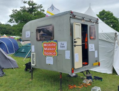 Here at Hackaday we’re neither estate agents or in the want-ads business, so we’re unaccustomed to property promotion. We’re still not immune to the attraction of a portable makerspace to take to events though, and this one provides a very practical basis. It started life as what Brits call a Luton van body, a box van, and inside it’s gained a small kitchen, benches and shelves either side, and up in the space over the cab, a double bed. Sadly the laser cutter and 3D printers aren’t included.


