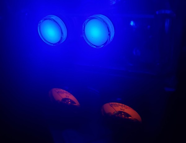
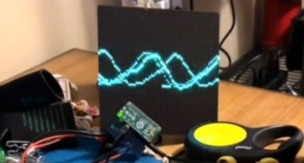
It may be hard to believe, but it’s time for the Hackaday Prize again! The 2023 Hackaday Prize was announced last weekend at Hackaday Berlin, and entries are already pouring in. The first-round challenge is all about “Re-engineering Education,” which means you’ve got to come up with a project idea that helps push back the veil of ignorance somehow. Perhaps you’ve got a novel teaching tool in mind, or a way to help students learn remotely. Or maybe your project is aimed at getting students involved and engaged. Whatever it is — and whatever the subject matter; it doesn’t just have to be hacking-adjacent — get an entry together, build a team, and get to work. The first round closes on April 25, so get to it!
Visual Ear Demonstrates How The Cochlea Works
The cochlea is key to human hearing, and it plays an important role in our understanding of complex frequency content. The Visual Ear project aims to illustrate the cochlear mechanism as an educational tool.
The cochlea itself is the part of the ear that converts the pressure waves of sound into electrical signals for the brain. Different auditory frequencies excite different parts of the cochlea. The cells in the different parts of the cochlea then send signals to the brain corresponding to the sound it has picked up.
The Visual Ear demonstrates similar behavior on a strip of addressable LEDs. Lower LEDs coded in the red part of the color spectrum respond to low frequency audio. Higher LEDs step through yellow, green, and up to blue, and respond to the higher frequencies in turn. This is achieved at a high response rate with the use of a Teensy 4.0 running a Fast Fourier Transform on incoming audio, and then outputting signals to run a string of WS2812B LEDs. The result is a visual band display of 104 bands spanning 43 Hz up to 16,744 Hz, which covers most but not all of the human range of hearing.
It’s an impressive display, and one that makes a great music visualizer, too. When teaching the physics of human hearing and the cochlea, we can imagine such a tool would be quite useful.
Continue reading “Visual Ear Demonstrates How The Cochlea Works”
Tour A PCB Assembly Line From Your Armchair
Those of us who build our own electronics should have some idea of the process used to assemble modern surface-mount printed circuit boards. Whether we hand-solder, apply paste with a syringe, use a hotplate, or go the whole hog with stencil and oven, the process of putting components on boards and soldering them is fairly straightforward. It’s the same in an industrial setting, though perhaps fewer of us will have seen an industrial pick-and-place line in action. [Martina] looks at just such a line for us, giving a very accessible introduction to the machines and how they are used. Have a look, in the video below the break.
It’s particularly interesting as someone used to the home-made versions of these machines, to see the optical self-alignment and the multiple pick-and-place tools which are beyond the simpler pick-and-place machines you’ll find in a hackerspace. Multiple machines in a line are also beyond hackerspaces, so the revelation that the first machine is deliberately run slowly to avoid the line backing up is a valuable one.
At the end of the line is the reflow oven itself, through which the boards pass on a belt through carefully graded hot air zones. Certainly a step up from a toaster oven with an Arduino controller!
Sadly not all of us will be lucky enough to have such a line at our disposal, but pick-and-place projects come up here quite often. We did a teardown on the feeders from a Siemens machine a couple of years ago.
Continue reading “Tour A PCB Assembly Line From Your Armchair”
Design Files Released For The PR2 Robot
It’s always great fun to build your own robot. Sometimes, though, if you’re doing various projects or research, it’s easier to buy an existing robot and then use it to get down to business. That was very much the role of the Willow Garage PR2, but unfortunately, it’s no longer in production. However, as covered by The Robot Report, the design files have now been released for others to use.
The PR2 was built as an advanced platform with wide-ranging capabilities. It was able to manipulate objects with its 7-degrees-of-freedom end effectors, as well as visualize the real world with a variety of complex sensor packages. Researchers put it to work on a variety of tasks, from playing pool to fetching beers and even folding laundry. The latter one is still considered an unsolved problem that challenges even the best robots.
Rights to the PR2 robot landed in the hands of Clearpath Robotics, after Willow Garage was shut down in 2014. Clearpath is now providing access to the robot’s design files on its website. This includes everything from wiring diagrams and schematics, to assembly drawings, cable specs, and other background details. You’ll have to provide some personal information to get access, but the documentation you desire is all there.
We actually got our first look at the PR2 robot many years ago, way back in 2009. If you decide to build your own from scratch, be sure to hit us up on the tipsline.
Printing A Brutalist Kitchen Timer
A kitchen timer is one of those projects that’s well defined enough to have a clear goal, but allows plenty of room for experimentation with functionality and aesthetics. [Hggh]’s exploration of the idea is a clean, Brutalist kitchen timer.
The case for [Hggh]’s kitchen timer is 3D printed with openings for a TM1637 four digit, seven segment display and for a KY-040 rotary encoder with knob attached. The internals are driven by an ATmega328P powered from a 18650 cell with a DW01-P battery protection chip and a TP4056 chip for charging. On the back of the case is a power switch and USB-C connector for power. It looks like the 3D printed case was sanded down to give it a smooth matte surface finish.
All the project files, including the STLs, OpenSCAD code, and KiCAD design, are available on GitHub. This Brutalist kitchen timer project is a nice addition to some of the kitchen timers we’ve featured in the past, including a minimalist LED matrix timer and a Nixie timer with keypad.
Rubik’s Cube Solver Does It In 4.56 Seconds
Solving Rubik’s Cubes is a learnable skill. However, to compete at the top level, you’ll have to train hard. Speed cubers can solve a 3×3 cube in under ten seconds these days, after all. [aaedmusa] was a long way off that speed, but his robot is an absolute demon that solves at a rapid pace.
The robot relies on a Teensy 4.1 microcontroller to run the show, paired with its Ethernet kit for connectivity. It runs six stepper motors via TMC2208 drivers, enabling it to directly actuate each face of the cube. Purists will note, however, that the steppers are fitted with adapters that slot directly into modified center squares on the cube. A regulation Rubik’s, this is not.
The design doesn’t feature a machine vision system to capture the state of the cube. Instead, the cube’s status must be input to a web app on an attached computer. Once the cube’s state is loaded into the program, though, the mechanical job of solving the cube can be achieved in under five seconds. Even with six actuators, that’s not fast enough to beat the human world record of 3.47 seconds, but it’s still pretty darn good.
It’s funny to think that way back in 2011, both robots and humans were so much slower at solving cubes. If only all the world’s problems were as simple as a jumbled up toy from the 1970s.
Continue reading “Rubik’s Cube Solver Does It In 4.56 Seconds”
Why Do Rifa Capacitors Fail?
Anyone who works with older electronic equipment will before long learn to spot Rifa capacitors, a distinctive yellow-translucent component often used in mains filters, that is notorious for failures. It’s commonly thought to be due to their absorbing water, but based upon [Jerry Walker]’s long experience, he’s not so sure about that. Thus he’s taken a large stock of the parts and subjected them to tests in order to get to the bottom of the Rifa question once and for all.
What he was able to gather both from the parts he removed from older equipment and by applying AC and DC voltages to test capacitors, was that those which had been used in DC applications had a much lower likelihood of exhibiting precursors to failure, and also a much longer time before failure when connected to AC mains.
Indeed, it’s only at the end of the video that he reveals one of the parts in front of him is an ex-DC part that’s been hooked up to the mains all the time without blowing up. It’s likely then that these capacitors didn’t perform tot heir spec only when used in AC applications. He still recommends replacing them wherever they are found and we’d completely agree with him, but it’s fascinating to have some light shed on these notorious parts.