Share Your Projects: Making Helpful PCBs

When it comes to things that hackers build, PCBs are a sizeable portion of our creative output. It’s no wonder – PCB design is a powerful way to participate in the hardware world, making your ideas all that more tangible with help of a friendly PCB fab. It’s often even more lovely when the PCB has been designed for you, and all you have to do is press “send” – bonus points if you can make a few changes for your own liking!

A lot of the time, our projects are untrodden ground, however, and a new design needs to be born. We pick out connectors, work through mechanical dimensions, figure out a schematic and check it with others, get the layout done, and look at it a few more times before sending it out for production. For a basic PCB, that is enough – but of course, it’s no fun to stop at ‘basic’, when there’s so many things you can do at hardly any cost.

Let’s step back a bit – you’ve just designed a board, and it’s great! It has all the chips and the connectors you could need, and theoretically, it’s even supposed to work first try. Now, let’s be fair, there’s an undeniable tendency – the more PCBs you design, the better each next one turns out, and you learn to spend less time on each board too. As someone with over two hundred PCBs under her belt, I’d like to show you a bunch of shortcuts that make your PCB more helpful, to yourself and others.

There’s a few ways that you can share your PCB projects in a more powerful way – I’d like to point out a few low-hanging fruits, whether README.md files or markings on the PCB itself. I’ve been experimenting quite a bit with external and embedded documentation of PCBs, as well as PCB sharing methods, got some fun results, and I’d like to share my toolkit through a few punchy examples and simple tricks. I’d also like to hear about yours – let’s chat! Continue reading “Share Your Projects: Making Helpful PCBs”

An RPi-Powered Multi-DX7/TX816 Style Synth

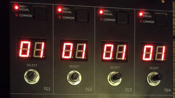
[Kevin] over at Simple DIY ElectroMusic Projects has released a complete DIY modular design for simulating the classic 80s Yamaha TX816 DX/FM modular digital synthesizer. This beast of a synth was used by the cool bands of the 80s as well as TV studios, and ownership of the original machine is an expensive investment. But with the power of modern hackable electronics, and the MiniDexed firmware running bare-metal on a Raspberry Pi getting access to a compatible synth doesn’t have to break the bank.

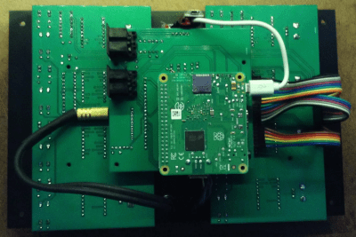
[Kevin] wanted to emulate the look and feel of the original TX816 aesthetic, developing a custom PCB handling the user interface for four of the eight channels, and a second acting as an interface to the Raspberry Pi using a Pico. Also sitting on this PCB is the GY-PCM5102 I2S DAC, and the MIDI connectors needed to connect to the system controller. Both PCBs, including a PCB-based front panel, were developed with KiCAD. The firmware for the Pico part of the system can be found on the firmware GitHub. The video demo (embedded below) shows off the system running a very 80s-sounding rendition of Holst’s famous ‘Jupiter’ from the planet series, and we all agree it sounds pretty sweet. For a complete rundown of the build, here are the links for the blog series for ease of access: Intro, PCBs, Panel, Build Guide, Mechanical, Pico/TX816 IO code, and finally usage. Phew!
If MiniDexed sounds familiar, that is because we featured another of [Kevin’s] earlier MiniDexed projects a little while ago.

Continue reading “An RPi-Powered Multi-DX7/TX816 Style Synth”

A miniature 486 desktop PC running Lemmings

Tiny 3D Printed Gaming PC Contains Real Retro Hardware

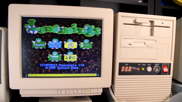
Emulators are easy and convenient, but for some retrocomputing enthusiasts nothing comes close to running classic software on actual era-appropriate hardware. This can become a problem, though, for those into vintage PC gaming: old PCs and their monitors are notoriously large and heavy, meaning that even a modest collection will quickly fill up a decent family home. There is a solution however, as [The Eric Experiment] demonstrates in his latest video. He designed and built a 3D-printed mini PC that runs on an actual 486 processor.

An ordinary desktop motherboard would have required a rather large case to begin with, so [Eric] started his project by buying an old industrial PC board. Such a device has the processor and all main motherboard components sitting on an ISA card, which then connects to other ISA cards through a backplane. This way, a complete system with expansion cards can be made way more compact than even the sleekest desktop PCs of the time. An SD-card-to-IDE converter makes for an extremely slim hard drive replacement, while a Gotek floppy emulator allows the system to boot as if there’s actually a floppy drive present.

A small 486 tower case being assembled
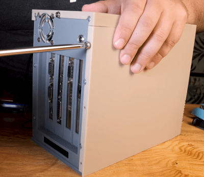
Even the side panels slide in exactly like they do on real PC cases.

All of this is pretty neat to begin with, but by far the most impressive parts of the Tiny 486 project are the enclosures that [Eric] designed for the PC and its accompanying monitor. Both were modelled off real-world examples and are accurate down to the smallest details: the tilting stand that clips onto the base of the monitor for instance, or the moving latch on the faux 5.25″ floppy drive. That latch operates a cleverly hidden door that reveals the USB connector for the floppy emulator. The compulsory seven-segment LED display on the mini tower’s front panel now finally serves a useful purpose – indicating which floppy image is currently active.

Sporting an Intel 486-DX4 100 MHz processor, 32 MB of RAM, a Tseng ET4000 video card and an ESS Audiodrive for sound, the tiny 486 can run DOS or Windows 95, although performance in the latter is a bit limited due to the lack of a local-bus video card. It’s perfectly fine for most DOS games though, and a lot more practical than a full-sized desktop PC.

There are several ways to make a tiny game PC, like using PC/104 standard boards or repurposing old network equipment. The crucial part needed to turn it into a gaming machine is a proper sound card, which you can even build from scratch if needed. Thanks for the tip, [Nathan]!

Continue reading “Tiny 3D Printed Gaming PC Contains Real Retro Hardware”

Parametric Design With Tinkercad

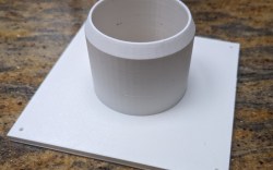
Tinkercad is like the hamburger helper of 3D design. You hate to admit you use it, and you know you should put in more effort, but — darn it — it’s easy, and it tastes pretty good. While I use a number of CAD programs for serious work, sometimes, when I just want a little widget like a flange for my laser cutter’s exhaust, it is just easier to do it in a few minutes with Tinkercad. However, I heard someone complaining the other day that it wasn’t of any use anymore because they took away custom shape generators. That statement is only partially true. Codeblocks allow you to easily create custom parametric items for use in Tinkercad.

A Tinkercad-designed flange

There was a time when you could write Javascript to create custom shapes, and it is true that they removed that feature. However, they replaced it with Codeblocks which is much easier to use for their target audience — young students — and still very powerful.

If you’ve used parametric design in a professional package or even used something like OpenSCAD, you probably don’t need to be sold on the benefit. This is, of course, a simple form of it, but the idea is to define things as mathematical relationships. As an example, suppose you have a front panel with two rows of four holes for switches evenly spaced and centered. That would be easy to draw. But if you later decide the top row needs five holes and the bottom only needs three, it will be a fair amount of work. But if you have the math defining it right, you change a few variables, and the computer does the rest. Continue reading “Parametric Design With Tinkercad”

Jac Goudsmit and Ralf Porankiewicz at Supercon 2022

2022 Supercon: Jac And Ralf Explore The Secrets Of The Digital Compact Cassette

During the 1990s, music was almost invariably stored on CDs or cassette tapes. When the new millennium came around, physical formats became obsolete as music moved first to MP3 files, and later to network streams. But a few years before that big transition, there were several attempts at replacing the aging cassette and CD formats with something more modern. You might remember the likes of MiniDisc and Super Audio CD, but there were a few other contenders around.

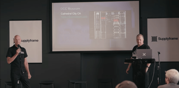
The Digital Compact Cassette, or DCC, was one such format. Released by Philips in 1992 as a replacement for the analog audio cassette, it failed to gain traction in the market and disappeared before most people had even heard of it. Not so for [Jac Goudsmit] and [Ralf Porankiewicz] however, who have spent years researching all aspects of the DCC system and shared some of the results in their 2022 Supercon talk.

[Ralf] is the curator of the DCC Museum in Cathedral City, California, which owns examples of all DCC equipment ever released, as well as several devices that never made it to market. He also aims to document the history of audio recording and DCC’s contribution to it, which goes further than you might think. For example, the audio compression format used in the DCC system, called PASC, was an early version of what would later become MP3 – though most histories of audio compression ignore this fact.

[Jac], for his part, made an extensive study of all the technical features of the DCC format. He has written numerous articles about his findings, first in the DCC FAQ and later by maintaining the relevant Wikipedia articles. He is running several projects aimed at keeping the format alive, often in collaboration with the DCC Museum.

[Jac] and [Ralf] begin their talk with a brief introduction to the system and its media. DCC players were designed to be compatible with analog audio cassettes, so DCC cartridges are the same basic size, though with a different type of tape inside. Playback devices contain a complex set of magnetic heads to read either the analog signals from classic tapes, or the digital data stored on DCCs.

One unique feature of DCC is Interactive Text Transfer Service, or ITTS, which is a separate data area on the tape that can hold additional information like song lyrics or even simple animations. It was intended to be displayed on players that supported it, but no such devices were ever released. Luckily, [Jac] and [Ralf] managed to find a rare ITTS decoder system used in a tape mastering facility, and were able to reveal the contents of this “secret track”, which is present on all prerecorded tapes, for the first time.

User-recorded tapes never had any ITTS data, and differed from prerecorded ones in several other ways, too. The most obvious difference was that professionally-made tapes could be indexed by song title, while home-made ones could only jump to track numbers. [Jac] and [Ralf] are however working to enable all the professional features on home-made tapes as well, through a number of software and hardware projects.

The most basic software needed is an encoder and decoder for the PASC format, which [Jac] developed from existing MP1 sofware. But to explore some of the more obscure hardware features, he had to reverse-engineer several different DCC players. This led him to discover many interesting half-finished features: the ITTS data sector is one example, but he also found out that some players send ready-to-use VU meter data to their front panel, even though they are unable to display that information.

[Jac] was also one of the first people to buy the DCC-175 portable DCC player when it was released in 1995. This was the only DCC player ever sold with a computer interface, allowing direct transfer of digital audio between a computer and a DCC tape. The parallel port interface and its accompanying Windows 9x software are completely obsolete and unusable with modern PCs, so [Jac] is working on directly accessing the data from the DCC-175 through a custom cable. He’s making good progress: he already figured out the electrical interface and wrote some software that enables him to control the tape recorder directly.

We can’t help but be impressed by the amount of effort both [Jac] and [Ralf] have put into understanding and documenting all the intricacies of a long-obsolete audio format. Thanks to their efforts, we can still appreciate the impressive technology behind DCC – even if it never came close to replacing its analog cousin.

Continue reading “2022 Supercon: Jac And Ralf Explore The Secrets Of The Digital Compact Cassette”

Assembly Language 80’s Minicomputer Style

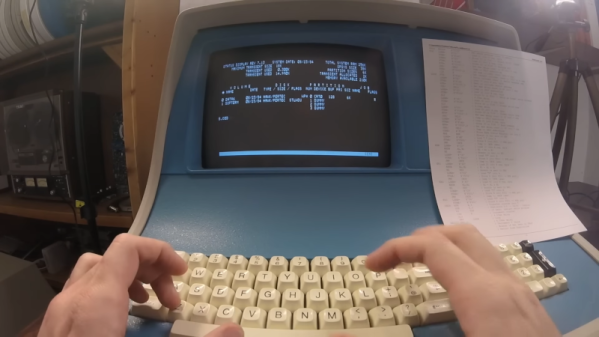
In the days before computers usually used off-the-shelf CPU chips, people who needed a CPU often used something called “bitslice.” The idea was to have a building block chip that needed some surrounding logic and could cascade with other identical building block chips to form a CPU of any bit width that could do whatever you wanted to do. It was still harder than using a CPU chip, but not as hard as rolling your own CPU from scratch. [Usagi Electric] has a Centurion, which is a 1980s-vintage minicomputer based on a bitslice processor. He wanted to use it to write assembly language programs targeting the same system (or an identical one). You can see the video below.

Truthfully, unless you have a Centurion yourself, the details of this are probably not interesting. But if you have wondered what it was like to code on an old machine like this, you’ll enjoy the video. Even so, the process isn’t quite authentic since he uses a more modern editor written for the Centurion. Most editors from those days were more like CP/M ed or DOS edlin, which were painful, indeed.

The target program is a hard drive test, so part of it isn’t just knowing assembly but understanding how to interface with the machine. That was pretty common, too. You didn’t have a lot of help from canned routines in those days. For example, it was common to read an entire block from a hard drive, tape, or drum and have to figure out what part of it you were actually interested in instead of, say, opening a file and reading a stream of characters.

If nothing else, fast forward over to the 25-minute mark and see what a hard drive from that era looked like. Guess how much storage was on that monster? If you guessed more than 10 MB, you probably didn’t live through the 1980s. We won’t even guess what the price tag was, but you can bet it was spendy.

If you think entering programs like this is painful, try a front panel. That made paper tape seem like a great thing.

Continue reading “Assembly Language 80’s Minicomputer Style”

A Loving Look Inside Vacuum Fluorescent Displays

Everyone knows we’re big fans of displays that differ from the plain old flat-panel LCDs that seem to adorn most devices these days. It’s a bit boring when the front panel of your widget is the same thing you stare at hour after hour while using your phone. Give us the chunky, blocky goodness of a vacuum fluorescent display (VFD) any day of the week for visual interest and retro appeal.

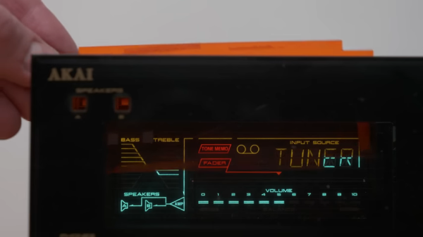
From the video below, it seems like [Posy] certainly is in the VFD fandom too, rolling out as he does example after example of unique and complicated displays, mostly from audio equipment that had its heyday in the 1990s. In some ways, the video is just a love letter to the VFD, and that’s just fine with us. But the teardowns do provide some insights into how VFDs work, as well as suggest ways to tweak the overall look of a VFD.

For example, consider the classy white VFDs that graced a lot of home audio gear back in the day. It turns out, the phosphors used in those displays weren’t white, but closer to the blue-green color that VFDs are often associated with. But put a pink filter between the display and the world, and suddenly those turquoise phosphors look white. [Posy] does a lot of fiddling with the stock filters to change the look of his VFDs, some to good effect, others less so.

As for the internals of VFDs, [Posy]’s look at a damaged display reveals a lot about how they work. With a loose scrap of conductor shorting one of the cathodes inside the tube, the damaged VFD isn’t much to look at, and is beyond reasonable repair, but it’s kind of cool to examine the spring mechanisms that take up slack as the cathodes heat up and expand.

Thanks to [Posy] for this heartfelt look into the VFDs of yesterday. If you need more about how VFDs work, we’ve covered that before, too.

Continue reading “A Loving Look Inside Vacuum Fluorescent Displays”