Hackaday Prize 2023: Over-the-Top Programmable Resistor Looks The Part And Performs

Every once in a while we get wind of a project that we’re reluctant to write up for the simple reason that it looks too good to be true. Not that projects need to be messy to be authentic, mind you, but there are some that are just so finished and professional looking that it gives us a bit of pause. [Sebastian]’s programmable precision resistor is a shining example of such a project

While [Sebastian] describes this as “a glorified decade resistance box,” and technically that’s exactly right — at its heart it’s just a bunch of precision resistors being switched into networks to achieve a specific overall resistance — there’s a lot more going on here than just that. The project write-up, which has been rolling out slowly over the last month or so, has a lot of detail on different topologies that could have been used — [Sebastian] settled on a switched series network that only requires six relays per decade while also minimizing the contribution of relay contact resistance to the network. Speaking of which, there’s a detailed discussion on that subject, plus temperature compensation, power ratings, and how the various decades are linked together.

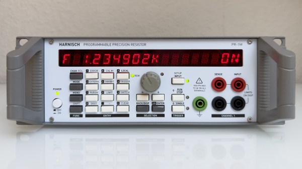
For as much that’s interesting about what’s under the hood, we’d be remiss to not spend a little time praising the exterior of this instrument. [Sebastian] appears to have spared no expense to make this look like a commercial product, from the rack-mount enclosure to the HP-esque front panel. The UI is all discrete pushbuttons and knobs with a long string of 16-segment LEDs — no fancy touch-screens here. The panel layout isn’t overly busy, and looks like it would be easy to use with some practice. We’d love to hear how the front and rear panel overlays were designed, too; maybe in a future project update.

This honestly looks like an instrument that you’d pay a princely sum to Keithley or H-P to own, at least back in the late 1990s or so. Kudos to [Sebastian] for the attention to detail here.

Ask Hackaday: Why Retrocomputing?

I recently dropped in on one of the Vintage Computer Festival events, and it made me think about why people — including myself — are fascinated with old computer technology. In my case, I lived through a lot of it, and many of the people milling around at VCF did too, so it could just be nostalgia. But there were also young people there.

Out of curiosity, I asked people about the appeal of the old computers on display there. Overwhelmingly, the answer was: you can understand the whole system readily. Imagine how long it would take you to learn all the hardware and software details of your current desktop computer CPU. Then add your GPU, the mass storage controllers, and your network interface. I don’t mean knowing the part numbers, specs, and other trivialities. I mean being able to program, repair, and even enhance it.

Continue reading “Ask Hackaday: Why Retrocomputing?”

Examining Test Gear From Behind The Iron Curtain

Back in 1978, an oscilloscope was an exotic piece of gear for most homebrewers. We expect they were even more rare in private hands behind the iron curtain, and [Thomas Scherrer] shows us a Soviet X1-7B combination oscilloscope and spectrum analyzer (he thinks, at least, it is a spectrum analyzer) that he got working.

The Soviet scope is clearly different with its Cyrillic front panel. Luckily, Google Translate was up to the task of decoding a picture of the device. However, the differences aren’t just cosmetic. The scope also has a very interesting rotating bezel around the round CRT. You can see a video of the 8.2 kg scope below.

A quick look inside looks pretty conventional for a scope of that era that used all transistors in the circuitry. The rotating bezel, though, also controls something that looks like a big mechanical switch and cavity or, perhaps, a big mechanical variable component of some kind.

Satisfied that the insides were in reasonable shape, [Thomas] was ready to try turning it on. We want to say it went well, but… there was censored audio, along with a loud noise, right after it was plugged in. Troubleshooting centered on what was producing a burned smell, but a quick examination didn’t turn up anything obvious, despite being localized to the power circuitry. The fuse didn’t blow, oddly, and — even more puzzling — the unit was off when plugged in!

It turns out the input power filter leaked to the chassis. Since he had a ground on the chassis, that explained the failure, and while it was annoying, it was better than getting a shock with a hot chassis. The second plug in went better.

It finally did work, at least somewhat, although he never explored some of the odd features the scope appears to have. We love the old boat anchor scopes but don’t see many Soviet instruments, at least not those of us on this side of the Atlantic.

We do see a few Soviet-era computers now and again. As for the fuse not blowing, it was shorted before the fuse, but apparently, fuses don’t always blow when you expect them to, anyway.

Continue reading “Examining Test Gear From Behind The Iron Curtain”

OLED Display Lets Vintage PC Engage Turbo Mode In Style

Back in the 486 days, it was common to see a “Turbo” button on the front panel of many PCs, which was used to toggle between the CPU’s maximum speed and a slower clock rate that was sometimes necessary for compatibility with older software. Usually an LED would light up to show you were running at this higher speed, or if your machine was very fancy, it might even have a numerical display that would show the current CPU frequency.

[Joshua Woehlke] wanted to add a similar display to his 486, but figured that with modern technology, he could do something a bit more interesting. Especially when he realized that the spot on his case where the two-digit LED display would have originally been mounted was the perfect size to hold a common 0.96″ SSD1306 OLED. From there it was just a matter of wiring it up to an Arduino and writing some code to display different graphics depending on the computer’s current CPU speed.

Just like the frequency indicators of yore, the Arduino doesn’t actually measure the CPU’s frequency, it’s simply reading the state of the Turbo LED on the front panel. When the LED is off the Arduino shows an image of a i8088 CPU on the screen to indicate the computer is running in compatibility mode, and when the LED is on, the screen shows the Cyrix Cx486 DX2 logo. When the button hasn’t been pressed in awhile, the display defaults to a star field screensaver.

Regular readers may recall we recently covered a similar project that used an Arduino to add a little flair to an era appropriate seven-segment LED display. We’d say there’s still a good deal of romanticism about computers having a big “TURBO” button you can smash whenever you feel the need for speed.

486 Gets Animated Turbo Button Thanks To Arduino

There was a point in time, excruciatingly brief, in which desktop computers often had a large “TURBO” button on their front panel. Some even featured an LED display that would indicate the current CPU frequency, providing visual conformation that your machine had leaped to a blistering 66 MHz.

The 486 that [someyob] is restoring had the Turbo button, but sadly there was just a simple LED to show whether or not it was engaged. But there was a window in the front panel where it seemed like a numerical display was intended to go, so they decided to wire up their own CPU indicator by sensing the state of the Turbo LED with an Arduino Pro Mini.

Now to modern audiences, this might seem like cheating. After all, the Arduino isn’t actually measuring the CPU speed, nor is it directly controlling it (that’s still done by the original Turbo button wiring). But the truth is, even back in the day, the CPU frequency displays faked it — they just toggled between showing two predefined frequencies depending on the state of the button. The arrangement [someyob] has come up with does the same thing, except now there’s some extra processing power in the mix, so the display can show some slick animations as it switches between 33 and 66 Mhz.

In the GitHub repository, [someyob] has provided the Arduino source code and schematics showing how the microcontroller was shoehorned into the existing front panel wiring without compromising its functionality. There’s even a brief video below that shows the display in operation.

Like the idea but don’t have a 486 laying around? Don’t worry. We’ve seen a similar panel built for modern machines that  just doesn’t look the part, it actually manages to be functional.

Continue reading “486 Gets Animated Turbo Button Thanks To Arduino”

A white Wii console sits on a grey table in the vertical orientation with its front facing the camera and its back away from the camera at a slight angle to the right. Next to it is a 2x sized replica which dwarfs the diminutive console. A purple light runs across the back edge of the table.

Wii XL Is Twice As Nice

The Wii was a relatively small console when it released, but it packed a big punch when it came to its game library and the impact it had on the industry. [Bringus Studios] wanted a Wii that physically matched the grandeur of one of Nintendo’s greatest successes, and built the Wii XL.

Basing the scale of this console around an 80 mm case fan, the final product has twelve times the volume of the original Wii. This leaves plenty of room for an unmodified original Wii, its power brick, and all the various cables and adapters necessary to bring the ports to the exterior of the case. To power the fan, [Bringus Studios] designed his first PCB to leach power off one of the USB connectors while still allowing data to pass through.The inside of a 3D printed and melamine case designed as a 2x copy of a Wii console. It is sitting flat on a grey table with the side removed so you can see the actual Wii console and power adapter mounted inside the case.

Given the size constraints of his 3D printers, he used melamine MDF for the sides and had to print the other panels in multiple pieces, resulting in some gapping in the front panel where the prints peeled off the print bed. We really love the use of a modular design that leaves room for future improvements, since no project is ever truly done.

Power is routed through a figure eight power connector on the outside to a female two prong plug on the inside while USB and HDMI are routed out the back via a combination panel connector intended for RV and boat use. If you don’t remember the Wii having HDMI out, that’s because it didn’t, but HDMI adapters are easy to come by for the machine.

In case you want to see more supersized projects checkout this giant XBox Series X or ponder if it would’ve been better with an enormous 555.

Continue reading “Wii XL Is Twice As Nice”

A 4-Player Arcade Hidden Inside A Coffee Table

[Ed] from 50% Awesome on YouTube wanted to build a retro gaming system with a decent screen size, but doesn’t have a great deal of space to site it in, so a good compromise was to make a piece of useful furniture and hide all the fun parts inside.

Building an arcade machine usually involves a lot of wiring

This video two-part build log shows a lot of woodwork, with a lot of mistakes (happy accidents, that are totally fine) made along the way, so you do need to repeat them. Essentially it’s a simple maple-veneered plywood box, with a thick lid section hosting the display and some repositioned speakers. This display is taken from a standard LG TV with the control PCB ripped out. The power button/IR PCB was prised out of the bezel, to be relocated, as were the two downwards-facing speakers. The whole collection of parts was attached to a front panel, with copious hot glue, we just hope the heavy TV panel was firmly held in there by other means!

Continue reading “A 4-Player Arcade Hidden Inside A Coffee Table”