Art of 3D printer in the middle of printing a Hackaday Jolly Wrencher logo

Brainstorming

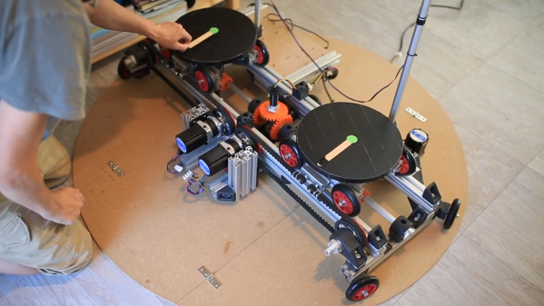
One of the best things about hanging out with other hackers is the freewheeling brainstorming sessions that tend to occur. Case in point: I was at the Electronica trade fair and ended up hanging out with [Stephen Hawes] and [Lucian Chapar], two of the folks behind the LumenPnP open-source pick and place machine that we’ve covered a fair number of times in the past.

Among many cool features, it has a camera mounted on the parts-moving head to find the fiducial markings on the PCB. But of course, this mean a camera mounted to an almost general purpose two-axis gantry, and that sent the geeks’ minds spinning. [Stephen] was talking about how easy it would be to turn into a photo-stitching macrophotography rig, which could yield amazingly high resolution photos.

Meanwhile [Lucian] and I were thinking about how similar this gantry was to a 3D printer, and [Lucian] asked why 3D printers don’t come with cameras mounted on the hot ends. He’d even shopped this idea around at the East Coast Reprap Festival and gotten some people excited about it.

So here’s the idea: computer vision near extruder gives you real-time process control. You could use it to home the nozzle in Z. You could use it to tell when the filament has run out, or the steppers have skipped steps. If you had it really refined, you could use it to compensate other printing defects. In short, it would be a simple hardware addition that would open up a universe of computer-vision software improvements, and best of all, it’s easy enough for the home gamer to do – you’d probably only need a 3D printer.

Now I’ve shared the brainstorm with you. Hope it inspires some DIY 3DP innovation, or at least encourages you to brainstorm along below.

At A Loss For Words? Try A Teleprompter

With everyone doing videos these days, you might want to up your narration game with a teleprompter. [Modern Hobbyist] can help. Since he does videos — like the one about the teleprompter below — we assume he built it out of his own need for the device. Actually, this is his second teleprompter. The first one was larger and not battery-powered, so this new version offers more portability. The camera shoots through the teleprompter screen so you can look right at the camera and still stay on script.

The project reuses some of the original teleprompter code, showing a text file via a Raspberry Pi. There’s also a control keyboard that lets you remotely control the scrolling speed. The real key to this project though is the 3D printed housing. Well, that and the reflective glass screen. Given that, you could do the actual text display in a number of ways.

Apparently, the portability of the build is limited somewhat by the weight of the camera. You could, of course, use something lighter or perhaps add some weight opposite to at least balance it a bit. The 3D printing files are on Thingiverse and the rest is on GitHub, so you can easily make changes if you want.

You would think we would see more teleprompter projects, and we do see some. We’ve also seen a hack to let you look through your laptop screen on video conferences.

Continue reading “At A Loss For Words? Try A Teleprompter”

Simple Mod Lets Quadruped Robot Stand And Walk

When it comes to locomotion, robots don’t typically do more than one thing at a time. Walkers stick to walking, and rollers stick to rolling. However, this simple method of enabling a cheetah-style quadruped to stand and even walk a little is pretty clever.

With just a couple of rigid struts attached to the shins of the rear legs, it becomes possible for the robot to lever itself up into a stable standing position, and even shuffle around a bit. Not bad for a couple bolted-on bits with no moving parts!

The robot style will look pretty familiar to some of our readers. It does resemble Boston Dynamics’ Spot but it’s closer to the MIT Mini Cheetah, whose design and brushless motors made for eye-catching agility and speed. It has inspired not just countless DIY efforts, but also kits of parts from overseas sellers.

The image here should make it clear how it works, but take a moment to also watch the short video embedded just below the page break, and see the process in action from beginning to end.

Continue reading “Simple Mod Lets Quadruped Robot Stand And Walk”

Real Minecraft Furnace Generates Electricity From Coal

There’s a furnace in Minecraft that is used to power all kinds of things in the game. [Joel] of Joel Creates decided he wanted to build a real-world replica, and did exactly that.

The furnace consists of a 30 cm aluminium cube, inside which the coal is burned. Thermoelectric generators (TEGs) are then placed on the sides of the furnace to turn the heat into useful electricity. The TEGs are installed in a sandwich of aluminium plates designed to maximize heat transfer through the TEGs themselves. They’re fitted with heatsinks to help create the maximum thermal gradient for greater power output. The entire setup is housed in a larger aluminium cube that’s finished to look like the Minecraft furnace — achieved by using a CNC machine to draw on the aluminium with high-temperature Sharpies.

With the coal a-burning inside, the furnace was able to generate enough power to run its own cooling and exhaust fans. It even had a little power left over to charge a phone. Overall though, [Joel] hopes that with some improvement, it can one day power his Minecraft car replica up to its top speed of 25 mph.

Continue reading “Real Minecraft Furnace Generates Electricity From Coal”

DIY Robotic Platform Aims To Solve Walking In VR

[Mark Dufour]’s TACO VR project is a sort of robotic platform that mimics an omnidirectional treadmill, and aims to provide a compact and easily transportable way to allow a user to walk naturally in VR.

Unenthusiastic about most solutions for allowing a user to walk in VR, [Mark] took a completely different approach. The result is a robotic platform that fits inside a small area whose sides fold up for transport; when packed up, it resembles a taco. When deployed, the idea is to have two disc-like platforms always stay under a user’s feet, keeping the user in one place while they otherwise walk normally.

It’s an ambitious project, but [Mark] is up to the task and the project’s GitHub respository has everything needed to stay up to date, or get involved yourself. The hardware is mainly focused on functionality right now; certainly a fall or stumble while using the prototype looks like it would be uncomfortable at the very best, but the idea is innovative. Continue reading “DIY Robotic Platform Aims To Solve Walking In VR”

Scramblepad Teardown Reveals Complicated, Expensive Innards

What’s a Scramblepad? It’s a type of number pad in which the numbers aren’t in fixed locations, and can only be seen from a narrow viewing angle. Every time the pad is activated, the buttons have different numbers. That way, a constant numerical code isn’t telegraphed by either button wear, or finger positions when punching it in. [Glen Akins] got his hands on one last year and figured out how to interface to it, and shared loads of nice photos and details about just how complicated this device was on the inside.

Just one of the many layers inside the Scramblepad.

Patented in 1982 and used for access control, a Scramblepad aimed to avoid the risk of someone inferring a code by watching a user punch it in, while also preventing information leakage via wear and tear on the keys themselves. They were designed to solve some specific issues, but as [Glen] points out, there are many good reasons they aren’t used today. Not only is their accessibility poor (they only worked at a certain height and viewing angle, and aren’t accessible to sight-impaired folks) but on top of that they are complex, expensive, and not vandal-proof.

[Glen]’s Scramblepad might be obsolete, but with its black build, sharp lines, and red LED 7-segment displays it has an undeniable style. It also includes an RFID reader, allowing it to act as a kind of two-factor access control.

On the inside, the reader is a hefty piece of hardware with multiple layers of PCBs and antennas. Despite all the electronics crammed into the Scramblepad, all by itself it doesn’t do much. A central controller is what actually controls door access, and the pad communicates to this board via an unencrypted, proprietary protocol. [Glen] went through the work of decoding this, and designed a simplified board that he plans to use for his own door access controller.

In the meantime, it’s a great peek inside a neat piece of hardware. You can see [Glen]’s Scramblepad in action in the short video embedded below.

Continue reading “Scramblepad Teardown Reveals Complicated, Expensive Innards”

A PCB with several points highlighted by a projection system

Augmented Reality Workbench Helps You To Debug Your Boards

No matter how advanced your design skills, the chances are you’ll need to spend some time chasing bugs in your boards after they come back from the assembly house. Testing and debugging a PCB typically involves a lot of cross-checking between the board, the layout and the schematic, which quickly becomes tiresome even for mildly complex designs. To make this task a bit easier, [Ishan Chatterjee] and colleagues at the University of Washington have designed the Augmented Reality Debugging Workbench, or ARDW for short.

The ARDW is a setup consisting of a lab workbench with an antistatic mat, a selection of measurement instruments and a PC. You can simply place your board on the bench, open the schematic and layout in KiCAD and start measuring and debugging your design as you normally would, but the real magic happens when you select a new icon in KiCAD that exports the schematic and layout to the ARDW system. From that moment, you can select components in your schematic and have them highlighted not only on the layout, but on the physical board in front of you as well. This is perhaps best demonstrated visually, as the team members do in the video embedded below.

The real-life highlighting of components is achieved thanks to a set of cameras that track the motion of everything on the desk as well as a video projector that overlays information on top of the PCB. All of this enables a variety of useful debugging features: for example, there’s an option to highlight pin one on all components, enabling a simple visual check of each component’s orientation. You can select all Do Not Populate (DNP) instances and immediately see if all highlighted pads are empty. If you’re not sure which component you’re looking at, just point at it with your multimeter probe and it’s highlighted on the schematic and layout. You can even place your probes on a net and automatically log the voltage for future reference, thanks to a digital link between the multimeter and the ARDW software.

In addition to designing and building the ARDW, the team also performed a usability study using a group of human test subjects. They especially liked the ability to quickly locate components on crowded boards, but found the on-line measurement system a bit cumbersome due to its limited positional accuracy. Future work will therefore focus on improving the resolution of the projected image and generally making the system more compact and robust. All software is freely available on the project’s GitHub page, and while the current system looks a little complex for hobbyist use, we can already imagine it being a useful tool in production environments.

It’s not even the first time augmented reality has been used for PCB debugging: we saw a somewhat similar system at the 2019 Hackaday Superconference. AR can also come in handy during the design and prototyping phase, as demonstrated by this AR breadboard.

Continue reading “Augmented Reality Workbench Helps You To Debug Your Boards”