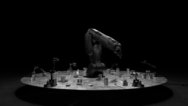
Sisyphus is an art installation by [Kachi Chan] featuring two scales of robots engaged in endless cyclic interaction. Smaller robots build brick arches while a giant robot pushes them down. As [Kachi Chan] says “this robotic system propels a narrative of construction and deconstruction.” The project was awarded honorary mention at the Ars Electronica’s Prix Ars 2022 in the Digital Communities category. Watch the video after the break to see the final concept.
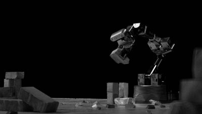
[Kachi Chan] developed the installation in pre-visualizations and through a series of prototypes shown in a moody process film, the second video after the break. While the film is quite short on details, you’ll see iterations of the robot arm and computer vision system. According to this article on the project [Kachi Chan] used Cinema 4D to simulate the motion, ROS for control, PincherX150 robotic arms modified with Dynamixel XM 430 & XL430 servo motors, and custom 3D prints.
We’ve covered another type of Sisyphus project, sand tables like this and the Sisyphish. Continue reading “Robot Repeatedly Rearranges Remnants In The Round”