[Drew Pilcher] needed durable, custom-wound coils with no core, and perfectly flat sides. Coils can be wound by hand, of course, but reliably creating perfect coils with thin wire and lots of layers requires some additional help. Happily, [Drew] shares his method for doing exactly that. Perhaps coming as no surprise, the key to repeatable, high-quality coils is good preparation and tools.
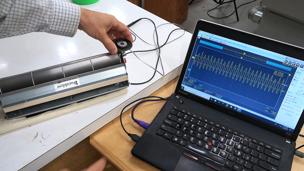
The most important part is the ability to rotate a spool for winding without having to take one’s hands off the workpiece. To accomplish this, a cheap, no-name power drill and foot pedal (made from the harvested trigger unit of the drill) forms the basis of [Drew]’s DIY winder. To make coils with precision, one must also count the number of turns. Thankfully, there is a simple solution for this; [Drew] used a cheap digital turn counter from Amazon. This economical device uses a magnet and sensor, so [Drew] simply stuck the magnet on the side of the drill’s chuck.
The spool is what the wire gets wound around to form the coil, and it will need to be removed from the coil afterwards. To accomplish this, [Drew] uses a brass shaft, metal washers, and some plastic spacers. A light coating of grease on the spool surfaces helps ensure things come apart properly in the end.
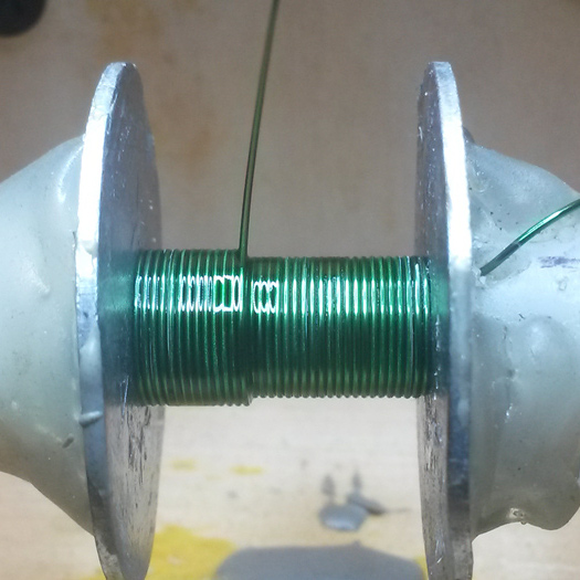
To actually make the coil, [Drew] recommends some means of magnification, and a supply of CA glue. Wind the wire as cleanly and closely as possible, and apply CA glue during the process to secure things. It takes some practice, but really clean windings are possible if done correctly.
For thick coils with a lot of layers, the CA glue will hold things together well enough, but for smaller coils [Drew] likes to give them a final coating of two-part epoxy. After things are completely set, the spool is disassembled and the inner core is pushed out as gently as possible.
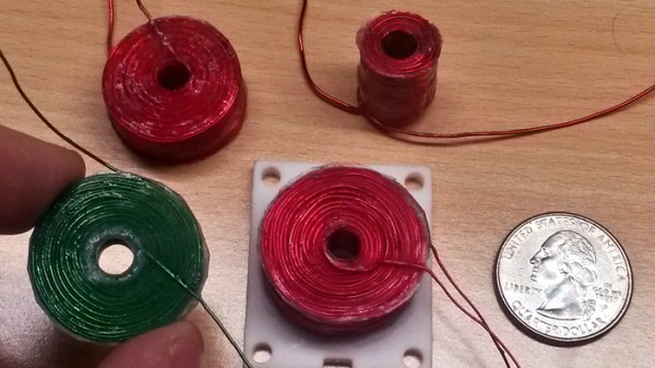
The result? A tightly-wound, durable coil with perfectly flat sides. It’s exactly the thing [Drew] needs for his upcoming coil gun project. How’s that work, you wonder? You can see the basics covered right here.


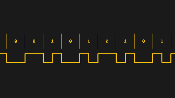

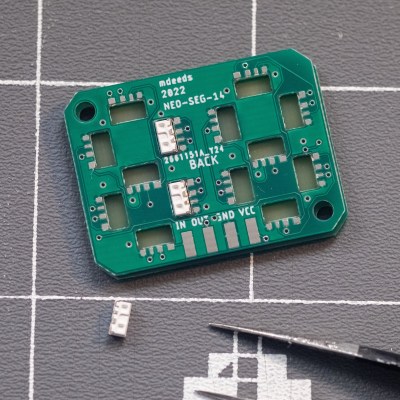 [Matt’s] build consists of a PCB filled with SK6812 side-mount LEDs, laid out in a typical 7-segment pattern. Each PCB features two 7-segment digits. The SK6812 LEDs can be driven in the same way as the famous WS2812B addressable LEDs, though they have the benefit of being more stable in color and brightness over a range of supply voltages.