The so-called Demon Core was a cursed object, a 6.2 kilogram mass of plutonium intended to be installed in a nuclear weapon. Instead, slapdash experimental techniques saw it feature in several tragic nuclear accidents and cause multiple fatalities. Now, you can build yourself a lamp themed after this evil dense sphere.
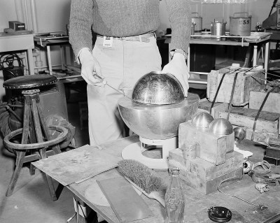
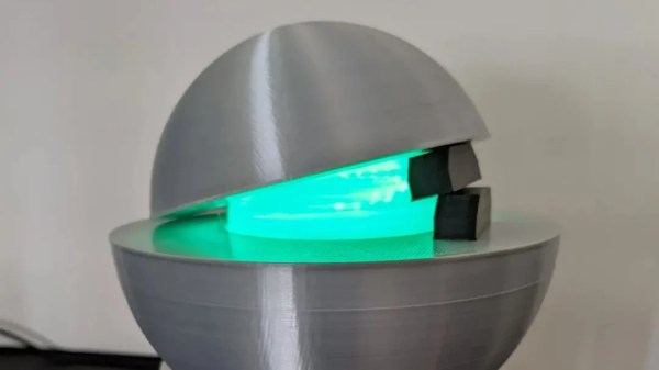
Creator [skelly] has designed the lamp to replicate the Slotin incident, where the spherical Demon Core was placed inside two half-spheres of beryllium which acted as neutron reflectors to allow it to approach criticality. Thus, the core is printed as a small sphere which is thin enough to let light escape, mimicking the release of radiation that doomed Louis Slotin. The outer spheres are then printed in silvery PLA to replicate the beryllium half-spheres. It’s all assembled atop a stand mimicking those used in the Los Alamos National Laboratory in the 1940s.
To mimic the Core’s deadly blue glow, the build uses cheap LED modules sourced from Dollar Tree lights. With the addition of a current limiting resistor, they can easily be run off USB power in a safe manner.
The Demon Core has become a meme in recent times, perhaps as a new generation believes themselves smart enough not to tinker with 6.2 kilograms of plutonium and a screwdriver. That’s not to say there aren’t still dangerous nuclear experiments going on, even the DIY kind. Be careful out there!


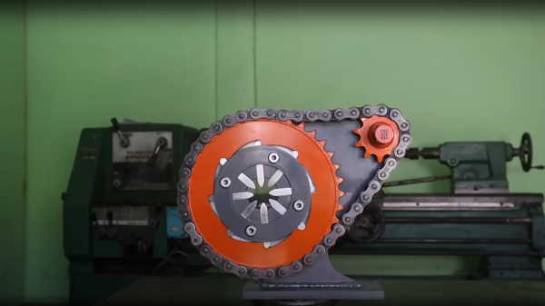
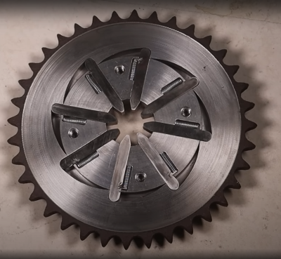 crimping profile. A small piece of steel was welded on to each, to allow a small spring to act on the finger, enabling it to retract at the end of the crimping action. We did spot the steel plate being held in place with a small magnet, prior to welding. The heat from that would likely kill off the magnetic field in a short space of time, but they’re so cheap as to be disposable items anyway.