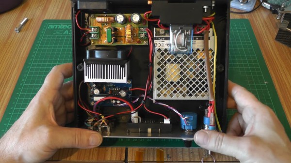
A Power Button For Raspberry Pi, Courtesy Of Device Tree Overlays

As a standard feature of the Linux kernel, device tree overlays (DTOs) allow for easy enabling and configuration of features and drivers, such as those contained within the standard firmware of a Raspberry Pi system. Using these DTOs it’s trivial to set up features like as a soft power-off button, triggering an external power supply and enable drivers for everything from an external real-time clock (RTC) to various displays, sensors and audio devices, all without modifying the operating system or using custom scripts.

It’s also possible to add your own DTOs to create a custom overlay that combines multiple DTO commands into a single one, or create a custom device tree binary (DTB) for the target hardware. Essentially this DTB is loaded by the Linux kernel on boot to let it know which devices are connected and their configuration settings, very similar to what the BIOS component with x86-based architectures handles automatically.

Ultimately, the DTB concept and the use of overlays allow for easy configuration of such optional devices and GPIO pin settings, especially when made configurable through a simple text file as on the Raspberry Pi SBC platform.

Continue reading “A Power Button For Raspberry Pi, Courtesy Of Device Tree Overlays”

Turn Timing Diagrams Into ASCII Art, For Friendlier Pasting

We all use text-based fields at one time or another, and being limited to ASCII only can end up being a limitation. That’s what led [Luke Wren] to create asciiwave, a fantastic tool that turns WaveDrom timing diagrams into ASCII art. Unlike images, ASCII timing diagrams are suitable for pasting into comment fields, change logs, or anywhere else that accepts text only. [Update: As the author kindly shared in the comments below, this tool’s original niche is pasting into HDL (e.g. Verilog) source code comments, where it has a special kind of usefulness.]

WaveDrom itself is a nifty JavaScript tool that we have covered before. It accepts timing diagrams expressed as JSON data, and renders nicely-readable digital timing diagrams as images directly inside one’s browser.

As cool and useful as that is, images can’t be pasted into text fields. That’s where asciiwave comes in. It reads the exact same format that WaveDrom uses, but generates an ASCII-art timing diagram instead. So if you’ve found WaveDrom useful, but wish you could generate ASCII versions, here’s your solution.

Quick-Swap Socket For Stemma QT Experiments

[kmatch98] shares a quick hack with us over at Hackaday.io – a 3D-printed socket for Adafruit Stemma QT-based I2C modules. Since Adafruit has standardized the dimensions for their Stemma QT boards, it’s possible to make a socket that would fit many different sensors at once, where the board just slides in.

This reminds us of sci-fi datadisks, or, thinking of something more grounded in reality, game console cartridges – except that here, the fun you’re having is from exploring all the different devices you can get to speak I2C. To make such a socket, you only need to 3D-print two plastic parts, put a JST-SH plug between them, and screw them together – if you want to modify these to your liking, .f3d sources are available. Now you no longer have to use fingernails or tin snips to take the JST-SH plug out of your modules!

[kmatch98] is no stranger to sharing his projects on Hackaday.io with us, and we’ve covered some of his larger projects before, like this CircuitPython-powered cyber-duck cyberdeck, or the 3D-printable Maypole braider machine!

The modified servo being calibrated on the left half of the screen, with some graphs of its operation being shown on the right half.

Servo Surgery Teaches Us DIY Encoder Implants

Today, we shall talk about how [Adam Bäckström] took a DS3225 servo and rebuilt it to improve its accuracy, then built a high-precision robot arm with those modified servos to show just how much of an improvement he’s got – up to 36 times better positional accuracy. If this brings a déjà vu feeling, that’s because we’ve covered his servo modifications before, but now, there’s more. In a year’s time since the last video came out, [Adam] has taken it to the next level, showing us how the modification is made, and how we ourselves can do it, in a newly released video embedded below.

After ordering replacement controller PCBs designed by [Adam] (assembled by your PCBA service of choice), you disassemble the servo, carefully setting the gearbox aside for now. Gutting the stock control board is the obvious next step, but from there, you don’t just drop the new PCB in – there’s more to getting a perfect servo than this, you have to add extra sensing, too. First, you have to print a spacer and a cover for the control board, as well as a new base for the motor. You also have to print (or perhaps, laser-cut) two flat encoder disks, one black and one white, the white one being eccentric. It only escalates from here!

Continue reading “Servo Surgery Teaches Us DIY Encoder Implants”

A Tshwatch on a table

TshWatch Helps You Learn More About Yourself

TshWatch is a project by [Ivan / @pikot] that he’s been working on for the past two years. [Ivan] explains that he aims to create a tool meant to help you understand your body’s state. Noticing when you’re stressed, when you haven’t moved for too long, when your body’s temperature is elevated compared to average values – and later, processing patterns in yourself that you might not be consciously aware of. These are far-reaching goals that commercial products only strive towards.

At a glance it might look like a fitness tracker-like watch, but it’s a sensor-packed logging and measurement wearable – with a beautiful E-Ink screen and a nice orange wristband, equipped with the specific features he needs, capturing the data he’d like to have captured and sending it to a server he owns, and teaching him a whole new world of hardware – the lessons that he shares with us. He takes us through the design process over these two years – now on the fifth revision, with first three revisions breadboarded, the fourth getting its own PCBs and E-Ink along with a, and the fifth now in the works, having received some CAD assistance for battery placement planning. At our request, he has shared some pictures of the recent PCBs, too!

Continue reading “TshWatch Helps You Learn More About Yourself”

Hackaday Links Column Banner

Hackaday Links: April 3, 2022

It’s that time of year again — the 2022 Hackaday Prize has officially launched, and we’re excited to see what it turns out. This year’s theme is “Sustainability, Resilience, and Circularity,” and just in time, too; if the last couple of years has taught us anything, it’s that we’ve got a lot of failure points built into the systems that run our world. As broken as things are, it’s tempting to just curl up in a ball and pretend everything’s fine, but that’s not how hackers respond to adversity. We need to control what we can control, and there’s plenty of work to be done. From sustainable energy ideas to ways to reduce the amount of stuff we throw away, from breathing new life into old equipment to building communities that can take care of themselves, there’s plenty of work to be done. So get over to the Hackaday Prize page, check out the launch summit video if you need some inspiration, and get hacking. And hurry up — things are only going to get better if people like us make it happen.

Continue reading “Hackaday Links: April 3, 2022”

Is Your Device Actually USB 3.0, Or Is The Connector Just Blue?

Discount (or even grey market) electronics can be economical ways to get a job done, but one usually pays in other ways. [Majenko] ran into this when a need to capture some HDMI video output ended up with rather less than was expected.

Faced with two similar choices of discount HDMI capture device, [Majenko] opted for the fancier-looking USB 3.0 version over the cheaper USB 2.0 version, reasoning that the higher bandwidth available to a USB 3.0 version would avoiding the kind of compression necessary to shove high resolution HDMI video over a more limited USB 2.0 connection.

The device worked fine, but [Majenko] quickly noticed compression artifacts, and interrogating the “USB 3.0” device with lsusb -t revealed it was not running at the expected speeds. A peek at the connector itself revealed a sad truth: the device wasn’t USB 3.0 at all — it didn’t even have the right number of pins!

A normal USB 3.0 connector is blue inside, and has both sets of pins for backward compatibility (five in the rear, four in the front) like the one shown here.

A USB 3.0 connection requires five conductors, and the connectors are blue in color. Backward compatibility is typically provided by including four additional conductors, as shown in the image here. The connector on [Majenko]’s “USB 3.0” HDMI capture device clearly shows it is not USB 3.0, it’s just colored blue.

Most of us are willing to deal with the occasional glitch or dud in exchange for low prices, but when something isn’t (and never could be) what it is sold as, that’s something else. [Majenko] certainly knows that as well as anyone, having picked apart a defective power bank module to uncover a pretty serious flaw.