Speech Synthesis On A 10 Cent Microcontroller

Speech synthesis has been around since roughly the middle of the 20th century. Once upon a time, it took remarkably advanced hardware just to even choke out a few words. But as [atomic14] shows with this project, these days it only takes some open source software and 10-cent microcontroller

The speech synth is implemented on a CH32V003 microcontroller, known for its remarkably low unit cost when ordered in quantity. It’s a speedy little RISC-V chip running at 48 MHz, albeit with the limitation of just 16 KB of Flash and 2 KB of SRAM on board.

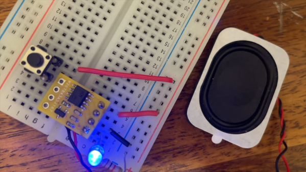
The microcontroller is hooked up to a speaker via a simple single-transistor circuit, which allows for audio output. [atomic14] first demonstrates this by having the chip play back six seconds of low quality audio with some nifty space-saving techniques to squeeze it into the limited flash available. Then, [atomic14] shows how he implemented the Talkie library on the chip, which is a softwarehttps://www.youtube.com/watch?v=RZvX95aXSdM implementation of Texas Instruments’ LPC speech synthesis architecture—which you probably know from the famous Speak & Spell toys. It’s got a ton of built in vocabulary out of the box, and you can even encode your own words with some freely available tools.

We’ve seen [atomic14] tinker with these chips before, too.

Continue reading “Speech Synthesis On A 10 Cent Microcontroller”

PCB Edge USB-C

Connector-Free Zone: PCB Edge As USB-C Interfaces

Sometimes when you’re making a PCB that you plan on programming over USB, but you only plan on plugging in a couple of times, it would be nice to make that connection without another BOM item. Over on GitHub [AnasMalas] has released a PCB edge USB-C connection symbol/footprint to do just that!

This isn’t the first PCB edge USB-C connector we’ve seen, but this one has some nice features. It’s available in both KiCad and EasyEDA formats, allowing you to easily add it into your preferred ECAD software. As well as supporting multiple software packages, there are two versions included: a 10-pin and 14-pin version. The 10-pin version has, on each side, 2 USB voltage pins, 2 ground pins, and a CC1 or CC2 pin on its respective side; this version is ideal if you’re looking to just supply power via the connector. The 14-pin version has all the pins of the 10-pin version with the addition of four data-positive and data-negative pins needed to relay information to the board, ideal if you’re planning on programming a microcontroller with this connection.

One important note is that, while most PCBs default to 1.6 mm thickness, if you use this connector you’ll need to drop that down to ~0.8 mm to properly interface with a common USB cable. [AnasMalas] also suggests using ENIG board finish to preserve the connectors on your USB cable.

For such a small and common connector, USB-C holds a ton of potential. Be sure to check out our series all about USB-C for more details.

Thanks to [Ben] for the tip.

Pi Port Protection PCB

We’re used to interfaces such as I2C and one-wire as easy ways to hook up sensors and other peripherals to microcontrollers. While they’re fine within the confines of a small project, they do have a few limitations. [Vinnie] ran straight into those limitations while using a Raspberry Pi with agricultural sensors. The interfaces needed to work over long cable runs, and to be protected from ESD due to lightning strikes. The solution? A custom Pi interface board packing differential drivers and protection circuits aplenty.

The I2C connection is isolated using an ISO1541 bus isolator from TI, feeding a PCA9615DP differential I2C bus driver from NXP. 1-wire is handled by a Dallas DS2482S 1-wire bus master and an ESD protection diode network. Even the 5-volt power supply is delivered through an isolated module.

Whether or not you need this Raspberry Pi board, this is still an interesting project for anyone working with these interfaces. If you’re interested, we’ve looked at differential I2C in the past.

The PC In Your Pico

We’re all used to emulating older computers here, and we’ve seen plenty of projects that take a cheap microcontroller and use it to emulate a classic home computer or gaming platform. They’re fun, but serve mostly as a way to relive old toys.

As microcontrollers become faster though it’s inevitable that the machines they can emulate become more powerful too, so we’re moving into the realm of emulating productivity machines from years past. An example is [Ilya Maslennikov]’s pico-286, which as its name suggests, is a 286 PC emulator for the Raspberry Pi Pico.

It has an impressive set of sound and video card emulations, can drive either a VGA or an HDMI monitor, and uses a PS/2 keyboard and mouse. If DOS games are your thing it should provide what you want, but it’s caught our eye because there was a time when a 286 DOS PC was a productivity machine. There’s a huge library of still-useful software for DOS, and thus the prospect of a handheld DOS PC still has some appeal. We’d love to see someone put this in a badge.

MS-DOS may no longer be for sale, but there are several ways to land an open-source DOS in 2025. FreeDOS is something of a powerhouse.

Flex PCB Underlies The Watch Of The Future

If you were at OpenSauce, you may have seen new Youtuber [Sahko] waltzing about with a retrofuturistic peice of jewelery that revealed itself as a very cool watch. If you weren’t, he’s his very first video on YouTube detailing the design and construction of this piece.  We’ve embedded it below, and it’s worth a watch. (Pun intended, as always.)

The build was inspired by the delightful amber LED dot-matrix display modules that circle the band of the watch. They go by HCMS2901, but [Sahko] recommends using the HCMS3901 as it’s both more 3.3V-tolerant and easier to find now. A challenge in mounting so many displays was the voltage on the supply rail dropping below the logic level; presumably the newer version does not have this problem to the same degree. Either way we love the look of these little displays and are pondering projects of our own that might include them.

He’s got quite a few wrapped around his wrist, so at full brightness, all these displays draw one amp. That explains why like the LED watches of the 1970s, the default state of the displays is “OFF”. Even with a LiPo pouch salvaged from a disposable vape, the runtime would only be half an hour at full brightness without that periodicity. Luckily [Sahko] included buttons on the band of the watch to activate it and control the brightness so it isn’t always blasting at full. There are also different modes available, including a really cool waterfall effect you can see in the video.

The band is an interesting choice, too: it’s just a flex PCB. There’s nothing backing it, aside from its own stiffeners, which makes us very curious how well this watch would hold up to daily use. There’s no clasp in the traditional sense, either: the band is closed by a 4-pin connector that doubles as both charge and the USB programmer for the stm32u08 microcontroller that runs the displays. Conveniently for a watch, this version of the stm32 has an RTC, so it keeps time as well. We dig the minimalism of this design; it’s a great contrast to the maximalism of wrapping your wrist in displays.

We’ve seen very similar displays on an edge-viewed watch, but a tiny amber LED matrix never gets old. If you wrapping your wrist in all those tiny LEDs is too impractically power-hungry, try using Nixie tubes.

We’re always watching for projects– wrist mounted clocks or otherwise– so if you’ve got the time, please drop us a tip.

Continue reading “Flex PCB Underlies The Watch Of The Future”

Transparent PCBs Trigger 90s Nostalgia

What color do you like your microcontroller boards? Blue? Red? Maybe white or black? Sadly, all of those are about to look old hat. Why? Well, as shared by [JLCPCB], this transparent Arduino looks amazing.

The board house produced this marvel using its transparent flexible printed circuit (FPC) material. Basically, the stuff they use for ribbon cables and flex PCBs, just made slightly differently to be see-through instead of vaguely brown.

The circuit in question is a Flexduino, an Arduino clone specifically designed to work on flexible substrates. It looks particularly good on this transparent material, with the LEDs glowing and the white silkscreen for contrast. If you like what you see, you can order your own circuits using this material directly from JLCPCB’s regular old order form.

Most of all, this project reminds us of the 1990s. Back then, you could get all kinds of games consoles and other electronics with transparent housings. There was the beloved PlayStation Crystal, while Nintendo did something similar with the N64 while adding a whole line of tinted color and charcoal versions too. Somehow seeing a bit of the inside of things is just cool. Even if, in some cases, it’s just to avoid smuggling in prisons.

It took decades before you could get custom PCBs quickly and easily. Now, board houses are competing for the enthusiast (consumer?) market, and competition is spurring development of crazy stuff like transparent and even glow in the dark PCBs. What next? We’re thinking edible, ROHS and WEEE be damned. Drop your thoughts in the comments.

Thanks to [George Graves] for the tip!

Split Keyboard Uses No PCB

When [daniely101] wanted a split keyboard, he decided to build his own. It wound up costing $25 to create a wireless board with no custom PCB required. Each half has its own microcontroller, and the whole thing connects via Bluetooth. While we don’t mind making a PCB, we can appreciate that you could change your mind easily with this wiring scheme.

The 3D printed case holds the keys, and then it is just a matter of carefully soldering the keys to the microcontrollers. Of course, each side also has to have its own battery. The ZMK firmware is split in half, one part for each side of the keyboard. The nRF52840 CPUs have plenty of wireless connectivity. The keys are set in rows and columns, so the amount of soldering back to the controller is manageable.

While we applaud the wireless design, it does seem odd that you have to charge both halves and turn them on and off separately. But that’s the nice thing about a design like this — you could modify the design to not have a split. Or, you could allow one flexible wire pair to run across for power. Of course, you could modify the layout, including adding or deleting keys.

You might consider adding a pointing device. At least you don’t have to pull out a saw.

Continue reading “Split Keyboard Uses No PCB”