Big Clive Hacks LED Bulbs With OpenSCAD

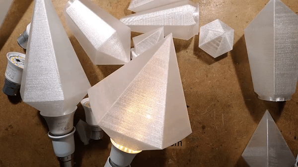
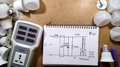
After accidentally crushing the plastic envelope on a cheap LED light bulb, [bigclivedotcom] figured out he could make custom ones using OpenSCAD in any shape he wants. He previously hacked a bunch of these inexpensive LED bulbs last month, discovering they all shared a similar circuit topology. All the ones he experimented with drove the LEDs hard, something that’s bound to reduce bulb lifetime. By reverse engineering the current control regulator, it turns out it is easy to adjust the drive current by changing a resistor or two. Reducing the current should not only increase lifetime, but could allow repurposing the bulb for other uses, such as decorative lighting.

Tweaking the LED Current

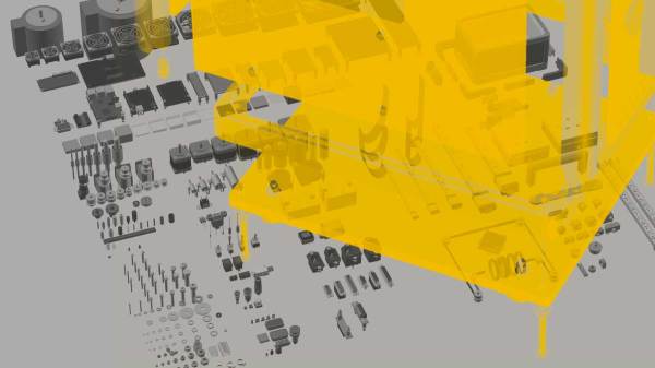
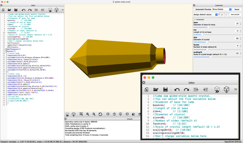
Three OpenSCAD scripts are provided which generate what he calls diamond, obelisk, and globe styles. Basic parameters for each style can be tweaked by the user, such as feature sizes and number of facets. He mentions the lack of OpenSCAD customizers in his script — this can easily be added as shown in the following example (this section of the User Manual on customizers explains the syntax). Note that you can’t make the slider generate real numbers, only whole numbers, which is why the scaling factor is multiplied by 10.

Adding Parameter Customization Sliders is Easy

These fancy globes can be used as night lights and possibly outdoor lighting, if you can make a good seal with the base. Custom chandeliers, anyone? Indicator lamps for very large panels? Any other ideas? If you want to explore the LED lifetime issue further, inveterate tinkerer Ted Yapo wrote a deep dive into the mythical 100,000 hour LED bulb. Thanks to [Cliff Claven] for the tip.

Continue reading “Big Clive Hacks LED Bulbs With OpenSCAD”

Micro Quadcopter Designed In OpenSCAD

Quadcopters are fantastical things, and now come in a huge variety of flavours, from lithe featherweight racers to industrial-grade filming rigs worth tens of thousands of dollars. The Beatle-1 from [masterdezign] comes in at the smaller scale, and its body was created entirely in code.

To create the Beatle-1, [masterdezign] used OpenSCAD, a 3D modelling program that uses code rather than visual tools for producing geometry. Thus, with a series of Boolean operations, extrusions and rotations, a basic lightweight quadcopter frame is created in a handful of lines of text. Then, it’s just a simple job of 3D printing the parts, wiring up four Olimex F1607 motors and hooking up a flight controller and the little drone is ready for takeoff.

The Beatle-1 serves as not only a fun flying toy but also a great example of applying OpenSCAD modelling techniques to real-world applications. Parts are available on Thingiverse for those wishing to roll their own. 3D printed drone frames are popular, and we’ve seen a few around these parts before. Video after the break.

Continue reading “Micro Quadcopter Designed In OpenSCAD”

OpenSCAD Prints Woodworking Aid

Home-based 3D printing is getting pretty unremarkable. Sure, printers aren’t as ubiquitous as, say, PCs. But you wouldn’t be any more surprised if your neighbor had a 3D printer than if you found out they had a drill press. In fact, sometimes the real value of 3D printing something isn’t to make a working part, but to make up something that helps you create other things using methods other than printing. That’s exactly what [iqless] does when he uses his printer to make some jigs to help him easily build shelves. (Video, embedded below.)

The issue is making dowel joints for the shelve’s feet. Sure, you could just drill a piece of scrap wood as a template, but with a 3D printer you can do better. Using OpenSCAD, it is possible to create a parameterized jig that fits exactly the job at hand.

Continue reading “OpenSCAD Prints Woodworking Aid”

Quick 3D-Printed Airfoils With These OpenSCAD Helpers

You know how it is. You’re working on a project that needs to move air or water, or move through air or water, but your 3D design chops and/or your aerodynamics knowledge hold you back from doing the right thing? If you use OpenSCAD, you have no excuse for creating unnecessary turbulence: just click on your favorite foil and paste it right in. [Benjamin]’s web-based utility has scraped the fantastic UIUC airfoil database and does the hard work for you.

While he originally wrote the utility to make the blades for a blower for a foundry, he’s also got plans to try out some 3D printed wind turbines, and naturally has a nice collection of turbine airfoils as well.

If your needs aren’t very fancy, and you just want something with less drag, you might also consider [ErroneousBosch]’s very simple airfoil generator, also for OpenSCAD. Making a NACA-profile wing that’s 120 mm wide and 250 mm long is as simple as airfoil_simple_wing([120, 0030], wing_length=250);

If you have more elaborate needs, or want to design the foil yourself, you can always plot out the points, convert it to a DXF and extrude. Indeed, this is what we’d do if we weren’t modelling in OpenSCAD anyway. But who wants to do all that manual labor?

Between open-source simulators, modelling tools, and 3D printable parts, there’s no excuse for sub-par aerodynamics these days. If you’re going to make a wind turbine, do it right! (And sound off on your favorite aerodynamics design tools in the comments. We’re in the market.)

Finding Perfect Part Fits With The Goldilocks Approach (and OpenSCAD)

There is something to be said for brute force or trial-and-error approaches to problems, especially when finding a solution has an empirical element to it. [Tommy] perceived that to be the case when needing to design and 3D print servo horns that would fit factory servos as closely as possible, and used OpenSCAD to print a “Goldilocks array” from which it was possible to find a perfect match for his printer by making the trial and error process much more efficient. By printing one part, [Tommy] could test-fit dozens of options.

What made doing this necessary is the fact that every 3D printer has some variance in how accurately they will reproduce small features and dimensions. A 6.3 mm diameter hole in a CAD model, for example, will not come out as exactly 6.3 mm in a 3D-printed object. It will be off by some amount, but usually consistently so. Therefore, one way around this is to empirically determine which measurements result in a perfect fit, and use those for production on that specific 3D printer.

That’s exactly what [Tommy] did, using OpenSCAD to generate an array of slightly different sizes and shapes. The array gets printed out, servos are test-fitted to them, and whichever option fits best has its dimensions used for production. This concept can be implemented in any number of ways, and OpenSCAD makes a decent option due to its programmatic nature. Interested in OpenSCAD? It will run on nearly any hardware, and you can get up and running with the basics in probably less than ten minutes.

Copying High Security Keys With OpenSCAD And Light

The ability to duplicate keys with a 3D printer is certainly nothing new, but so far we’ve only seen the technique used against relatively low hanging fruit. It’s one thing to print a key that will open a $15 Kwikset deadbolt from the hardware store or a TSA-approved “lock” that’s little more than a toy, but a high-security key is another story. The geometry of these keys is far more complex, making them too challenging to duplicate on a consumer-level printer. Or at least, you’d think so.

Inspired by previous printed keys, [Tiernan] wanted to see if the techniques could be refined for use against high security Abloy Protec locks, which are noted for their resistance to traditional physical attacks such as picking. The resulting STLs are, unsurprisingly, beyond the capabilities of your average desktop FDM printer. But with a sub-$300 USD Anycubic Photon DLP printer, it’s now possible to circumvent these highly regarded locks non-destructively.

Of course, these keys are far too intricate to duplicate from a single picture, so you’ll need to have the physical key in hand and decode it manually. [Tiernan] wisely leaves that step of the process out, so anyone looking to use this project will need to have a good working knowledge of the Abloy Protec system. Hopefully this keeps bad actors from doing anything too nefarious with this research.

Once you have the decoded values for the key you want to duplicate, you just need to provide them to the OpenSCAD library [Tiernan] has developed and print the resulting STL on your sufficiently high-resolution printer. Generally speaking, the parts produced by resin-based printing have a high tensile strength but are very brittle, so perhaps not the kind of thing you want to stick in your expensive Abloy lock. That said, there are some “Tough Resin” formulations available now which produce parts that are at least as strong as those made with thermoplastics. So while the printed keys might not be strong enough for daily use, they’ll certainly work in a pinch.

Try NopSCADlib For Your Next OpenSCAD Project

Most readers of this site are familiar by now with the OpenSCAD 3D modeling software, where you can write code to create 3D models. You may have even used OpenSCAD to output some STL files for your 3D printer. But for years now, [nophead] has been pushing OpenSCAD further than most, creating some complex utility and parts libraries to help with modeling, and a suite of Python scripts that generate printable STLs, laser-ready DXFs, bills of material, and human-readable assembly instructions complete with PNG imagery of exploded-view sub-assemblies.

Recently [nophead] tidied all of this OpenSCAD infrastructure up and released it on GitHub as NopSCADlib. You can find out more by browsing through the example projects and README file in the repository, and by reading the announcement blog post on the HydraRaptor blog. Some functionality highlights include:

  • a large parts library full of motors, buttons, smooth rod, et cetera
  • many utility functions to help with chamfers, fillets, precision holes, sub-assemblies, and BOM generation
  • Python scripts to automate the output of STLs, DXFs, and BOMs
  • automatic creation of documentation from Markdown embedded in your OpenSCAD files
  • automatic rendering of exploded subassemblies

All that’s missing is a nice Makefile to tie it all together! Try it out for your next project if you – like us – get giddy at the thought of putting your 3D projects into version control before “compiling” them into the real world.

We’ve discussed some complex OpenSCAD before: Mastering OpenSCAD Workflow, and An OpenSCAD Mini-ITX Computer Case.