OpenSCAD Gives You Parametric Boxes

OpenSCAD is one of the most powerful 3d modeling applications around. Its beauty is in its simplicity; if you need a box, you can just write the code for a box. If you need some bit of plastic to keep your 3D printer running, you can just write the code for that bit of plastic. Like all programming languages, OpenSCAD is only really powerful if you have a huge back-catalog of various components ready for reuse. That’s where [Mark]’s library for hinged boxes comes in handy. Every type of box you would ever want to create, from boxes with covers, magnet closures, or cases for your glasses is easily accessible with just a few lines of code.

The work presented here is an OpenSCAD script to generate two-piece hinged boxes, with rounded corners, a lid, interlocking rims, and optional snap fit, magnet, or screw closures. As you would expect from OpenSCAD, everything in this script is parametric. You can change any measurement or simply delete entire sections of the box.

The included examples consist of a small mini-Altoids tin-sized ‘Bee Box’ with a snap-fit lid. All of the relevant dimensions of the snap-fit lid are variables. Other examples include an eyeglass case and a box for small parts storage that interlock. If you have a few rolls of filament, a lot of time on your hands, and want to organize your workbench, you could do worse than checking out a few of these OpenSCAD boxes.

Mastering OpenSCAD Workflow

As you may have noticed in our coverage, we’re big fans of OpenSCAD around these parts. The fact that several of the Hackaday writers organically found and started using the parametric CAD package on their own is not only a testament to our carefully cultivated hive mind but also to the type of people it appeals to. Hackers love it because it allows you to model physical objects as if you were writing software: models are expressed in code, and its plain text source files can be managed with tools like git and make. If you’re a real Pinball Wizard you could design objects and export them to STL without ever using a graphical interface.

But as you might expect, with such power comes a considerable learning curve. OpenSCAD devotee [Uri Shaked] recently wrote in to share with us his workflow for designing complex interacting mechanisms, which serves as an excellent primer to the world of parametric design. From animating your models to recreating the “vitamins” of your build, his post contains plenty of tips that can help both new and veteran OpenSCAD users alike.

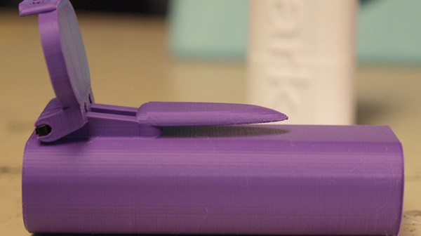
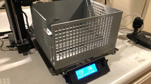
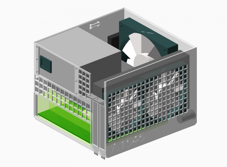
Perhaps the biggest takeaway from his post is that you should be thinking of your projects as a whole, rather than as individual models. [Uri] recalls his early attempts at designing mechanisms: designing each component individually, printing it out, and only then finding out if it fits together with the other pieces. This method of trial and error is probably familiar to anyone who’s designed their own 3D printed parts — but it’s slow and wastes materials. The alternative, as he explains it, is to design all of the pieces at the same time and “assemble” them virtually. This will allow you to check clearances and fitment without dedicating the time and materials to test it in the real world.

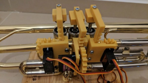
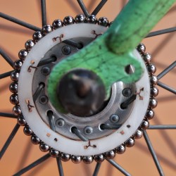
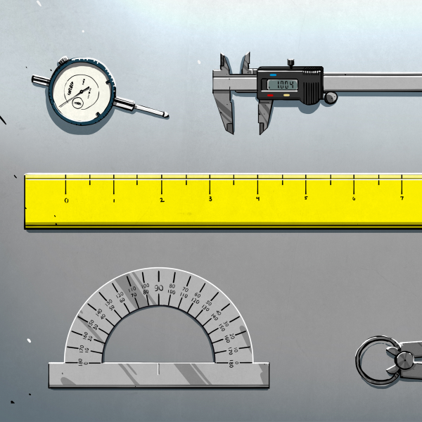
In fact, as [Uri] explains, you’re better off spending your time bringing real-world parts into OpenSCAD. By carefully measuring the hardware components you want to interact with (servos, gears, switches, etc), you can create facsimiles of them to use as a reference in your OpenSCAD project. As time goes on, you can build up your own library of drop-in reference models which will accelerate future designs.

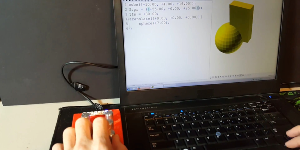
He also spends a little time talking about something that doesn’t seem to be terribly well known even among the OpenSCAD converts: you don’t have to use the built-in editor if you don’t want to. Since OpenSCAD source code files are plain text, you can write them in whatever editor you like. The OpenSCAD model viewer even has an option specifically for this scenario, which will cause it to update the rendered preview as soon as it detects the source has been updated. For [Uri] this means he can create his designs in Visual Studio Code with a constantly updating preview in another window.

If you’re looking for examples of what the parametric capabilities of OpenSCAD can do for you, we’ve got no shortage of excellent examples. From creating customized computer cases to saving time by using mathematically derived components. Our very own [Elliot Williams] even has a write up about that most glorious of OpenSCAD commands: hull().

An OpenSCAD Mini-ITX Computer Case

We’re no strangers to 3D printed enclosures here at Hackaday. From the plethora of printed Raspberry Pi cases out there to custom enclosures for electronic projects, small plastic boxes turn out to be an excellent application for desktop 3D printing. But as printers get bigger and filament gets cheaper, those little boxes don’t always need to be so little. We aren’t talking about running off boxes for your sneaker collection either, if you’ve got the time and the print volume, you could whip up an enclosure for your PC.

[Nirav Patel] writes in to share his impressive 3D printed Mini-ITX computer case project, which would be a neat enough trick in its own right, but he took the concept one step farther and made it a parametric design in OpenSCAD. This allows the user to input their particular hardware configuration and receive STL files for a bespoke case. The list of supported hardware isn’t that long yet, but with the OpenSCAD code up on GitHub and released under the BSD license, hopefully the community can improve on that as time goes on.

To keep things simple (and strong), [Nirav] implemented what he refers to as a “bucket” design. The majority of the case is a single print, which does take a long time (just shy of 40 hours on his Prusa i3 MK3), but nearly eliminates any post-printing assembly. Only the optional feet and the lid need to be printed separately. Threaded inserts are used throughout the design for mounting hardware, so you don’t run the risk of blowing out the printed holes during hardware changes or upgrades.

A particularly neat feature, and a testament to the power of OpenSCAD, is the fact that the case’s internal volume is calculated and embossed into the side of the design. Does this have any practical purpose? Not exactly, but [Nirav] thought it would be appealing to the Mini-ITX case modding community which apparently measures their accomplishments in liters of volume.

We’ve seen a 3D printed computer case before, but it used acrylic sheets and couldn’t be made without a large format printer. There’s something to be said for a project that can be completed on the hacker community’s favorite printer.

OpenSCAD Handles The Math In 3D Printed Holder For Magnetic Spheres

3D printed holder mounted to bike wheel, fitting precisely 38 magnetic spheres around its perimeter. Tedious math? Not if you make OpenSCAD do it.

Off-the-shelf components are great; the world and our work simply wouldn’t be the same without. But one of the constraints is that one has to design around them, and that’s what led [Antonio Ospite] to create a parametric design in OpenSCAD for a 3D printed holder which snugly fits a number of magnetic spheres around its diameter.

If that sounds a bit esoteric, it will become much clearer in the context of [Antonio]’s earlier work in making a DIY rotary encoder out of a ring of magnetic spheres. He found that such a ring in front of two Hall effect sensors was low in cost, high in precision, and thanks to 3D printing it also had a lot of potential for customizing. But hampering easy design changes was the need for the spheres to fit snugly around whatever shape was chosen for the hardware, which meant constraints on the encoder diameter.

In this case, [Antonio] wished to create an encoder that could be attached to a bicycle wheel but needed to know what outer diameter would best fit a ring of magnetic balls perfectly, given that the balls were each 5 mm. OpenSCAD did the trick, yielding a design that fit the bike wheel and spokes while perfectly nestling 38 magnetic balls around the outside edge with a minimum of wasted space.

OpenSCAD is a CAD program that’s really more like a programming language than anything else. For those who are not familiar with it, [Brian Benchoff] walked through how to make a simple object in OpenSCAD, and [Elliot] has sung the praises of a few advanced functions. Now that this project makes DIY encoders easier, perhaps they could be used to add intuitive new controls to OpenSCAD itself.

OpenSCAD: Tieing It Together With Hull()

What’s your favorite OpenSCAD command? Perhaps it’s intersection() or difference()? Or are you a polygon() and extrude() modeler? For me, the most useful, and maybe most often overlooked, function is hull(). Hull() does just what it says on the can — creates a convex hull around the objects that are passed to it as children — but that turns out to be invaluable.

Hull() solves a number of newbie problems: making things round and connecting things together. And with a little ingenuity, hull() can provide a nearly complete modelling strategy all on its own. If you use OpenSCAD and your creations end up with hard edges, or you spend too much time figuring out angles, or if you just want to experience another way to get the job done, read on!

Continue reading “OpenSCAD: Tieing It Together With Hull()”

Making Rubber Stamps With OpenSCAD

There’s an old saying that goes “If you can’t beat ’em, join ’em”, but around these parts a better version might be “If you can’t buy ’em, make ’em”. A rather large portion of the projects that have graced these pages have been the product of a hacker or maker not being able to find a commercial product to fit their needs. Or at the very least, not being able to find one that fit their budget.

GitHub user [harout] was in the market for some rubber stamps to help children learn the Armenian alphabet, but couldn’t track down a commercially available set. With a 3D printer and some OpenSCAD code, [harout] was able to turn this commercial shortcoming into a DIY success story.

Filling the molds with urethane rubber.

Rather than having to manually render each stamp, he was able to come up with a simple Bash script that calls OpenSCAD with the “-D” option. When this option is passed to OpenSCAD, it allows you to override a particular variable in the .scad file. A single OpenSCAD file is therefore able to create a stamp of any letter passed to it on the command line. The Bash script uses this option to change the variable holding the letter, renders the STL to a unique file name, and then moves on to the next letter and repeats the process.

This procedural generation of STLs is a fantastic use of OpenSCAD, and is certainly not limited to simple children’s stamps. With some improvements to the code, the script could take any given string and font and spit out a ready to print mold.

With a full set of letter molds generated, they could then be printed out and sealed with a spray acrylic lacquer. A mold release was applied to each sealed mold, and finally they were filled with approximately 200ml of Simpact urethane rubber from Smooth-On. Once the rubber cures, he popped them out of the molds and glued them onto wooden blocks. The end result looks just as good as anything you’d get from an arts and crafts store.

The process used here is very similar to the 3D printed cookie molds we’ve covered recently, though we have to assume these little morsels would not be nearly as tasty. Of course, if you had access to a small CNC machine you could cut the stamps out of the rubber directly and skip the mold step entirely.

Add Intuitiveness To OpenSCAD With Encoders

The first time I saw 3D modeling and 3D printing used practically was at a hack day event. We printed simple plastic struts to hold a couple of spring-loaded wires apart. Nothing revolutionary as far as parts go but it was the moment I realized the value of a printer.

Since then, I have used OpenSCAD because that is what I saw the first time but the intuitiveness of other programs led me to develop the OpenVectorKB which allowed the ubiquitous vectors in OpenSCAD to be changed at will while keeping the parametric qualities of the program, and even leveraging them.

All three values in a vector, X, Y, and Z, are modified by twisting encoder knobs. The device acts as a keyboard to

  1. select the relevant value
  2. replace it with an updated value
  3. refresh the display
  4. move the cursor back to the starting point

There is no software to install and it runs off a Teensy-LC so reprogramming it for other programs is possible in any program where rotary encoders may be useful. Additional modes include a mouse, arrow keys, Audacity editing controls, and VLC time searching.

Here’s an article in favor of OpenSCAD and here’s one against it. This article does a good job of explaining OpenSCAD.

Continue reading “Add Intuitiveness To OpenSCAD With Encoders”