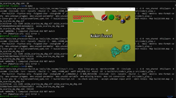
Old Phone Becomes MIDI Controller

MIDI controllers come in all shapes and sizes. Commercial products based on keyboards or matrixes of buttons are popular, but there’s nothing stopping you from whipping up your own creations out of whatever strikes your fancy. [Kevin] has done just that, turning an old telephone into a working MIDI device.

The phone in question is a Doro X20 wired landline phone. Being surplus to [Kevin’s] requirements left it ripe for the hacking. A Raspberry Pi Pico was wired in to the phone’s keypad, slimmed down with a hacksaw in order to allow it to neatly fit inside the original enclosure. Then it was a simple matter of whipping up some code to read the buttons and output MIDI data via the Pico’s serial output.

Later, [Kevin] brought the design into the modern world, setting it up to talk USB MIDI using the Pico’s onboard USB hardware. This makes using it with a computer a cinch, and lets [Kevin] control a DAW using the handset controller.

It’s a fun build, and one that shows how you can easily build your own MIDI hardware using nothing but a soldering iron, some buttons, and a modern microcontroller. From there, the sky really is the limit. Whether you like big knobs, easy playing, or have your own personal tastes, you can build what you like to suit your own style. When you do, drop us a line! Video after the break.

Continue reading “Old Phone Becomes MIDI Controller”

Restoring A Vintage Tube Tester To Its Former Glory

It can be difficult for modern eyes to make much sense of electronics from the 1960s or earlier. Between the point-to-point soldering, oddball components, and the familiar looking passives blown up to comical proportions like rejected props from “Honey, I Shrunk the Kids”, even experienced hardware hackers may find themselves struggling to understand what a circuit is doing. But that didn’t stop [Cat0Charmer] from taking the time to lovingly restore this Hickok Cardmatic KS-15874-L2 tube tester.

The good news was that the machine had nearly all of its original parts, down to the Hickok branded tubes in the power supply. Unfortunately it looks like a few heavy handed repairs were attempted over the years, with a nest of new wires and components intermixed with what [Cat0Charmer] actually wanted to keep. The before and after shots of individual sections of the machine are particularly enlightening, though again, don’t feel to bad if you still can’t make heads or tails of the cleaned up version.

Hiding new capacitors inside of the old ones.

As you’d expect for a machine of this age, many of the original components were way out of spec. Naturally the capacitors were shot, but even the carbon composition resistors were worthless after all these years; with some measuring 60% away from their original tolerances.

We particularly liked how [Cat0Charmer] hollowed out the old capacitors and installed the new modern ones inside of them, preserving the tester’s vintage look. This trick wasn’t always feasible, but where it was applied, it definitely looks better than seeing a modern capacitor adrift in a sea of 60’s hardware.

After undoing ham-fisted repairs, replacing the dud components, and installing some new old stock tubes, the tester sprung to life with renewed vigor. The previously inoperable internal neon lamps, used by the tester’s voltage regulation system, shone brightly thanks to all the ancillary repairs and changes that went on around them. With a DIY calibration cell built from the schematics in an old Navy manual, [Cat0Charmer] got the tester dialed in and ready for the next phase of its long and storied career.

We love seeing old hardware get restored. It not only keeps useful equipment out of the scrap heap, but because blending new and old technology invariably leads to the kind of innovative problem solving this community is built on.

Improved Technique For Resistive Divider Keypads

[Lauri Pirttiaho] from the [Swiss Knife of Electronics] channel explains how to simplify your resistive divider keypad design on Hackaday.io.

The usual method involves building a resistive ladder that gives unique and equally spaced voltages for each keypress. If you have just four or five discrete buttons, it isn’t terribly difficult, but if you have a 12- or 16-keypad matrix, things get complicated. [Lauri] looked into the past to come up with a better way, specifically a 646 page, 1 kg textbook from 1990 — Analogue Ic Design: The Current-Mode Approach by Toumazou, Lidgey, and Haigh. He learned that sometimes what’s hard to do in the voltage domain is easy in the current domain.

Normally you’d throw in some resistors to form different voltage dividers depending on which key is pressed, and read the resulting voltage off of a voltage divider with an ADC. But that means using the voltage divider equation, and the difference in voltage between keys can get very small. Dropping the voltage divider and measuring the current through a current mirror generates a linear voltage across its output load resistor that can be easily read by your microprocessor. And [Lauri] has posted an example of just such a program on his GitHub repository for an Arduino.

Heavy analog electronics, for sure, but something to keep in mind if you’re reading more than 12 keys. Do you have any examples of solving problems by looking into old and/or less-common techniques? Let us know in the comments below.

Continue reading “Improved Technique For Resistive Divider Keypads”

Historical Hackers: Ctesibius Tells Time

People are obsessed with the time and the weather. We’ve talked about the weather since we were all cave dwellers hunting with spears. But the time is a different matter. Sure, people always had the idea of the passage of time. The sun rising and setting gives a natural sense of days, but daylight and dark periods vary by the time of year and to get an accurate and linear representation of time turns out to be rather difficult. That is unless you are a Greek engineer living in Alexandria around 250 BC.

Legend has it that and engineer working in his father’s barbershop led him to discover not only the first working clock, but also the pipe organ, launching the field of pneumatics in the process. That engineer was named Ctesibius and while his story is mostly forgotten, it shows he has a place as a historical hacker.

You might think there were timekeeping devices before 250 BC, and that’s sort of true. However, the devices before Ctesibius had many limitations. For example, a sundial can tell time, but only if the sun is shining. At night or during a storm it is worthless.

Continue reading “Historical Hackers: Ctesibius Tells Time”

3D Printed Calipers Work Like Clockwork

Most of us use calipers when working with our 3D printers. Not [Albert]. He has a clockwork caliper design that he 3D printed. The STL is available for a few bucks, but you can see how it works in the video below. We don’t know how well it works, but we’ll stick with our digital calipers for now.

The digital readout on this caliper is more like a sophisticated watch. A window shows 10s of millimeters and two dials show the single digits and the number after the decimal point.

Continue reading “3D Printed Calipers Work Like Clockwork”

What Is Ultra Wideband?

If you’ve been following the world of mobile phone technology of late, you may be aware that Apple’s latest IPhones and AirTag locator tags bring something new to that platform. Ultra wideband radios are the new hotness when it comes to cellphones, so just what are they and what’s in it for those of us who experiment with these things?

An Apple AirTag being paired with an iPhone. Swisshashtag, CC BY-SA 4.0.

Ultra wideband in this context refers to radio signals with a very high bandwidth of over 500 MHz, and a very low overall power density spread over that  spectrum. Transmissions are encoded not by modulation of discrete-frequency carriers as they would be in a conventional radio system, but by the emission of wideband pulses of RF energy across that bandwidth.  It can exist across the same unlicensed spectrum as narrower bandwidth channelised services, and that huge bandwidth gives it an extremely high short-range data transfer bandwidth capability. The chipsets used by consumer devices use a range of UWB channels between about 3.5 and 6.5 GHz, which in radio terms is an immense quantity of spectrum. Continue reading “What Is Ultra Wideband?”

Flat Transformer Gives This PCB Tesla Coil Some Kick

Arguably, the most tedious part of any Tesla coil build is winding the transformer. Getting that fine wire wound onto a suitable form, making everything neat, and making sure it’s electrically and mechanically sound can be tricky, and it’s a make-or-break proposition, both in terms of the function and the aesthetics of the final product. So this high-output printed circuit Tesla should take away some of that tedium and uncertainty.

Now, PCB coils are nothing new — we’ve seen plenty of examples used for everything from motors to speakers. We’ve even seen a few PCB Tesla coils, but as [Ray Ring] points out, these have mostly been lower-output coils that fail to bring the heat, as it were. His printed coil generates some pretty serious streamers — a foot long (30 cm) in some cases. The secondary of the coil has 6-mil traces spaced 6 mils apart, for a total of 240 turns. The primary is a single 240-mil trace on the other side of the board, and the whole thing is potted in a clear, two-part epoxy resin to prevent arcing. Driven by the non-resonant half-bridge driver living on the PCB below it, the coil can really pack a punch. A complete schematic and build info can be found in the link above, while the video below shows off just what it can do.

Honestly, for the amount of work the PCB coil saves, we’re tempted to give this a try. It might not have the classic good looks of a hand-wound coil, but it certainly gets the job done. Continue reading “Flat Transformer Gives This PCB Tesla Coil Some Kick”