555-timer Charges Lead Acid Batteries

555-timer-charges-lead-acid-batteries

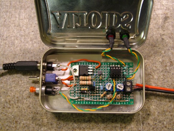
[Kenneth Finnegan] took the focus of a great design and redirected it to solve his own problem. What results is this lead acid battery charger based on the 555 timer. It’s not a top-of-the-line, all the bells and whistles type of charger. But it gets the job done with a readily available IC and no need to code for a microcontroller.

The original idea came from a solar battery charger entered in the 555 timer contest. The main difference in application between that and [Kenneth’s] application is the source. A solar array or wind turbine is limited on how much juice it can produce. But mains power can push a shocking (har-har) amount of current if you’re not paying attention. Herein lies the alterations to the circuit design. To control this he’s using a Laptop power supply as an intermediary and only implementing the constant current portion of the tradition 3-stage lead acid charging profile (those stages are explained in his write up).

He did a talk on the charger at his local radio club. You can see the 90-minute video after the break.

Continue reading “555-timer Charges Lead Acid Batteries”

Dot Matrix Printer Spits Out Any Tweet Mentioning @KWF

Earlier this month, [Kenneth] picked up an old dot matrix printer at the Silicon Valley Flea Market and subsequently found two cases of tractor feed printer paper. It’s a marriage made in heaven for a dot matrix twitter printer.

[Kenneth] used a BeagleBone – a tiny single board computer running Linux – to connect to the Internet and fetch any new tweets mentioning KWF every minute or so. The BeagleBone spits out these tweets over the USB port which is connected to the ancient printer by means of a cheap adapter cable.

Interestingly, [Kenneth] wrote the code for this project as a shell script. A lot of effort went into scrubbing the input of any escape characters, but he still implores his admirers to not attempt to break his project.

In case you’re wondering, at couple Twitter accounts announced this post’s headline to the Twitterverse when this story was published. This should have immediately sent [Kenneth]’s printer into motion, recording that harsh mistress that is sending a build log of a Twitter connected device into Hackaday.

After the break you can see [Kenneth]’s demo. Be sure to share this post on Twitter!

Video Review: STM32F0-Discovery Board

The STM32 Discovery boards are nothing new, we’ve looked at them several times. But the newest sibling in the line might be just the thing to make the leap from your steadfast 8-bit projects. We got our hands on it and recorded a video review.

The STM32F0-Discovery gives you a programmer and ARM Cortex-M0 chip all on one convenient board. The top portion is the ST-Link V2 programmer, and includes jumpers and a programming header which let it easily program off-board chips.

The included microcontroller is an STM32F051R8T6 which includes 64kb of program memory and 8kb of RAM. Coming in at $1.80-3.77 in single units and in a hand-solderable LQFP package this raises an eyebrow for our future projects. It has an 8 MHz internal oscillator with 6x PLL which means you can run at 48 MHz without an external crystal (check out [Kenneth Finnegan’s] PLL primer if you don’t know what this is).

The only thing holding us back is the development environment. ST provides everything you need if you’re on Windows, but we want a Linux friendly solution. We know other Discovery boards have worked under Linux thanks to this project. This uses the same ST-LINK V2 so it should work as well. If you want one of your own head over the ST page to see if they’re still giving away samples. There should be a button labeled “Register for your FREE KIT”.

Intro To Phase-Locked Loops

[Kenneth Finnegan] put up a lengthy primer on PLLs (Phase-Locked Loops). We really enjoyed his presentation (even the part where he panders to Rigol for a free scope… sign us up for one of those too). The concepts behind a PLL are not hard to understand, and [Kenneth] managed to come up with a handful of different demonstrations that really help to drive each point home.

A PLL is made up of three parts: a phase detector, a low pass filter, and a voltage controlled oscillator. It can do really neat things, like multiply clock speed (you see them in beefier chips like the ARM architecture all the time). The experiments seen in the video use a CD4046 chip which has two different types of phase detectors. The two signals displayed on the oscilloscope above compare the incoming clock signal with the output from the VCO. Depending on the type of phase detector used, and the quality of the low-pass filter, these might be tightly synchronized or wildly unstable. Find out why by watching the video embedded after the break.

Continue reading “Intro To Phase-Locked Loops”

Numitron Tube Tutorial

Nixies and VFDs are great displays, but when using them you’ve got to deal with some fairly high voltages, at least for the micro projects we see on Hack a Day. Luckily, there’s another ancient technology that can be driven at tiny voltages. [Kenneth] put up a great tutorial on Numitron tubes to show the Internet how to get these guys working.

Numitron tubes are like Nixies, but instead of the ten number-shaped filaments in each Nixie, Numitrons are old-school seven-segment displays. [Kenneth] picked up a few on ebay and the seller was kind enough to include a Russian data sheet. Each filament in his IV-9 Numitrons required about 20mA to light up, perfect for the constant current LED drivers [Kenneth] picked up

The test circuit consisted of an ATtiny2313 and an A6278 LED driver. The code on the ATtiny cycles the digits 0 through 9. This is sent through the LED driver and lights up the tiny filaments inside the tube. Check out the video after the break to see the Numitron in action

Continue reading “Numitron Tube Tutorial”

This Toy Intercom System Is Way Better Than A Pair Of Tin Cans And Some String

toy-intercom-system

On his blog, [Kenneth Finnegan] recently showed off a replica of a fun toy he used to play with as a kid, a telephone intercom system. The setup is pretty simple, requiring little more than a pair of analog phones, a battery, and a resistor.

The phones are connected to one another using a standard telephone cable, but [Kenneth] uses a 9v battery to introduce a small bias current into the loop, allowing the speakers at either end to hear one another. He also added a small LED into the circuit so that there is a visual indication as to when both handsets are off hook.

The setup is very simple at the moment, though [Kenneth] does have some ideas in mind to enhance his intercom system. He hopes to tweak the remote phone to ring when the local phone is picked up, among other things.

Telephone technology is nothing new, but for just a few dollars (or less) your kids can be entertained for hours as [Kenneth] was way back when.

Continue reading to see a short video overview of the phone system, and be sure to share your ideas for enhancing it in the comments section.

Continue reading “This Toy Intercom System Is Way Better Than A Pair Of Tin Cans And Some String”

ATtiny Hacks: SerialCouple – A Standalone Thermocouple ADC Board With Serial Out

ATtiny Hacks Theme Banner

serialcouple_thermocouple_adc_board

Since we are in the midst of featuring a wide assortment of ATtiny hacks, [Kenneth] wrote in to share a project he has been developing over the last few months, the SerialCouple.

Most all development platforms have the ability to function as an analog to digital converter, but you don’t always need a full-featured board when all you require is serial output for your computer. With his SerialCouple board, [Kenneth] is trying to take some complexity out of the process by building a standalone thermocouple ADC board. The SerialCouple is designed to take analog readings from a thermocouple, converting them to digital values that can be sent to any device over a serial connection. The grunt work is done by a Maxim MAX31855 chip, which converts the thermocouple’s analog data to digital temperature readings. The digital representation of the temperature is then retrieved by the on-board ATtiny2313, which sends the data out the serial port.

If a standalone thermocouple ADC board is something you’ve been looking for, be sure to swing by his site to take a look at his code and schematics.

Continue reading to see a short video demo that explains how the SerialCouple works.

Continue reading “ATtiny Hacks: SerialCouple – A Standalone Thermocouple ADC Board With Serial Out”