How can we convey to a world in which a 64-bit laptop can be a near-throwaway item, just how amazing a miniature laptop version of the 1980s Sinclair ZX Spectrum could have been? perhaps we don’t need to, because here in 2023 there’s a real one for all middle-aged geeks who had the original to drool over.
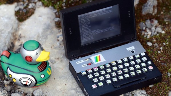
8-bit home computers were super-exciting for the kids of the day, but they were in no way portable and relied on a TV, frequently the family model in the living room. It’s safe to say that a portable version of one of those home computers, not in an Osborne-style luggable case but in a clamshell palmtop, would have been mind-blowing, so four decades later we’re fascinated by [Airrr17]’s portable Sinclair ZX Spectrum.
At its heart is a dev board using one of the STM32F4 series microcontrollers, and running the Spectrum as an emulator. Alongside that is an LCD, and perhaps what is physically the best part of this, a Spectrum keyboard complete with BASIC keyword decals, made with large-button tactile switches that have we think, printed paper on top. Add in a small lithium-polymer cell and associated electronics in a cute little palmtop case, and it’s about as good a portable Sinclair as we could have imagined. All the details can be found in a GitHub repository, and as if that weren’t enough there’s an assembly video we’ve placed below the break.
Continue reading “The Laptop Every British Kid Would Have Wanted For Christmas 1983”
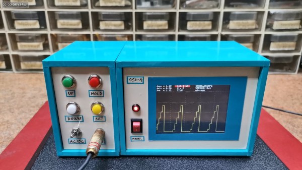
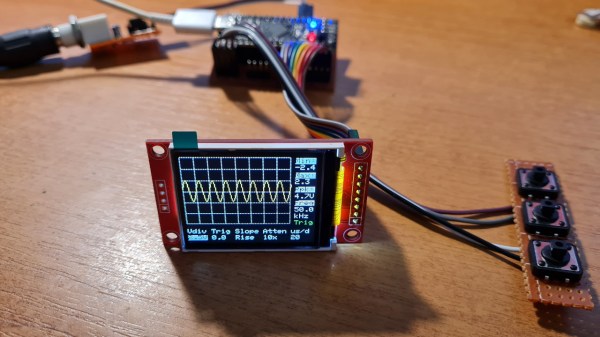
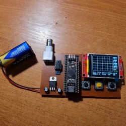 It’s hard to overshadow just how easy this scope is to build, use, and hack on. You really don’t need much in the way of parts, a protoboard will do, though you can also etch or order